
A pipe insulation layer structure based on jacket

A pipeline insulation layer and jacket type technology, which is applied in pipeline protection, heat preservation, and pipeline protection through heat insulation, etc. It can solve the problems of small connection between the sealing mechanism and the insulation sleeve, affecting the temperature of the medium inside the pipeline, and affecting the production and processing technology. , to eliminate the risk of falling off, improve the sealing effect, and ensure the effect of production and processing technology

Active Publication Date: 2020-12-15
大庆恒达丰建筑材料制造有限公司
View PDF8 Cites 0 Cited by
  • Summary
  • Abstract
  • Description
  • Claims
  • Application Information

AI Technical Summary

Problems solved by technology

However, there are the following problems when the current insulation sleeve is connected to the pipeline: 1. The sealing effect between the end of the insulation sleeve and the pipeline is poor, and the cold air from the outside will also enter the joint of the pipeline, which will affect the temperature of the medium inside the pipeline , affecting the subsequent production and processing technology; 2. When connecting the sealing mechanism, there is a small connection between the sealing mechanism and the insulation sleeve, and there is a risk of the sealing mechanism falling off

Method used


Image

  • A pipe insulation layer structure based on jacket
  • A pipe insulation layer structure based on jacket
  • A pipe insulation layer structure based on jacket

Examples


Embodiment Construction

[0024] Embodiments of the present invention will be described below with reference to the drawings. In the process, in order to ensure the clarity and convenience of illustration, we may exaggerate the width of the lines or the size of the constituent elements in the diagram.

[0025] In addition, the following terms are defined based on the functions in the present invention, and may be different according to the user's or operator's intention or practice. Therefore, these terms are defined based on the entire content of this specification.

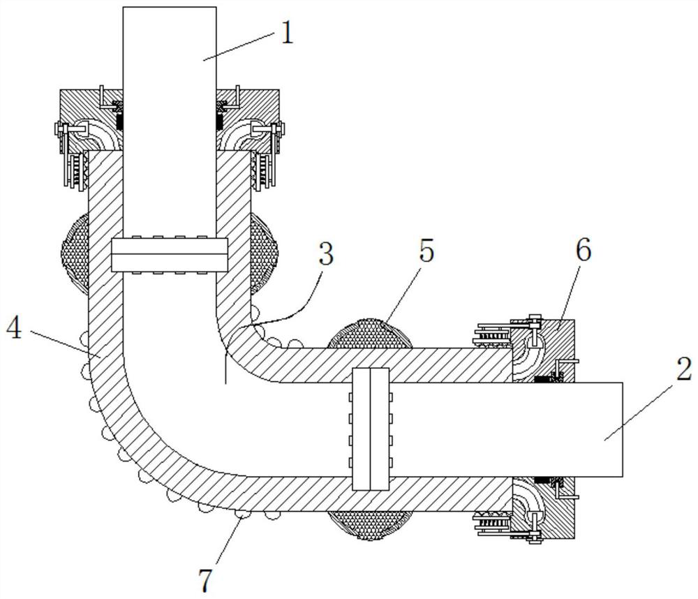
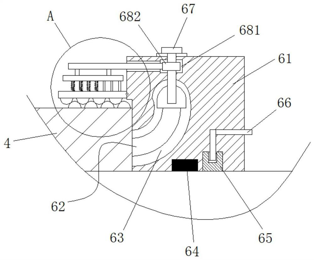
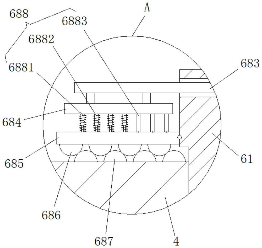
[0026] Such as Figure 1-4 As shown, a pipe insulation layer structure based on the jacket type includes an insulation cover body 4, and the middle section of the insulation cover body 4 is an arc-shaped structure. The cross-section of point 7 is a semicircular structure, and the anti-collision bump 7 is made of rubber; the insulation sleeve 4 is used to prevent external cold air from entering the pipeline, and the design of the arc st...


PUM


Abstract

The invention relates to a pipeline heat preservation layer structure based on the outer sleeve type. The structure comprises a heat preservation sleeve body, a bending pipe is arranged in the heat preservation sleeve body, the top end of the bending pipe is in abut joint with a vertical pipe, the right end of the bending pipe is in abut joint with a transverse pipe, the top end of the heat preservation sleeve body covers the bottom end of the vertical pipe, the right end of the heat preservation sleeve body covers the left end of the transverse pipe, heat preservation structures are arrangedon the two ends of the heat preservation sleeve body, and are arranged on the abut-joint positions of the transverse pipe and the bending pipe, seal mechanisms are arranged between the heat preservation sleeve body and the left end of the transverse pipe and between the heat preservation sleeve body and the bottom end of the vertical pipe, each seal mechanism comprises a seal annular shell, the seal annular shells are arranged on the periphery of the left end of the transverse pipe and the periphery of the bottom end of the vertical pipe, arc guide grooves are formed in the inner sides of theseal annular shells, an arc guide rod is arranged at the end of the heat preservation sleeve body, and the arc guide rod is arranged in the arc guide grooves. Exterior air can be prevented from entering the abut-joint position of a pipeline, the temperature of media in the pipeline is ensured, the subsequent production machining process is ensured, and the falling risk of the seal mechanisms can be removed.

Description

technical field [0001] The invention relates to the technical field of pipeline insulation layers, in particular to a jacket-based pipeline insulation layer structure. Background technique [0002] In the process of industrial production, it is often necessary to use pipelines to transport fluids, especially for the transportation of fluids between various devices in refining and chemical enterprises. Most of these fluids need to be transported with insulation to ensure that the internal medium can maintain a constant temperature in each process. This requires insulation of the pipes. [0003] One of the ways to insulate pipes is to put insulation sleeves around the pipes. However, there are the following problems when the current insulation sleeve is connected to the pipeline: 1. The sealing effect between the end of the insulation sleeve and the pipeline is poor, and the cold air from the outside will also enter the joint of the pipeline, which will affect the temperature...

Claims


Application Information

Patent Timeline
Patent Type & Authority Patents(China)
IPC IPC(8): F16L59/18F16L59/22
CPCF16L59/184F16L59/22
Inventor 倪立兵姚孝明张纪彬
Owner 大庆恒达丰建筑材料制造有限公司
Features
  • Generate Ideas
  • Intellectual Property
  • Life Sciences
  • Materials
  • Tech Scout
  • Unparalleled Data Quality
  • Higher Quality Content
  • 60% Fewer Hallucinations
Learn More