Video monitoring equipment for security protection and control system thereof
A video monitoring and control system technology, applied in the direction of closed-circuit television systems, mechanical equipment, supporting machines, etc., can solve the problems of inconvenient disassembly, inconvenient disassembly, poor convenience, etc., and achieve convenient disassembly, convenient disassembly and installation, and convenient maintenance Effect
- Summary
- Abstract
- Description
- Claims
- Application Information
AI Technical Summary
Problems solved by technology
Method used
Image
Examples
Embodiment 1
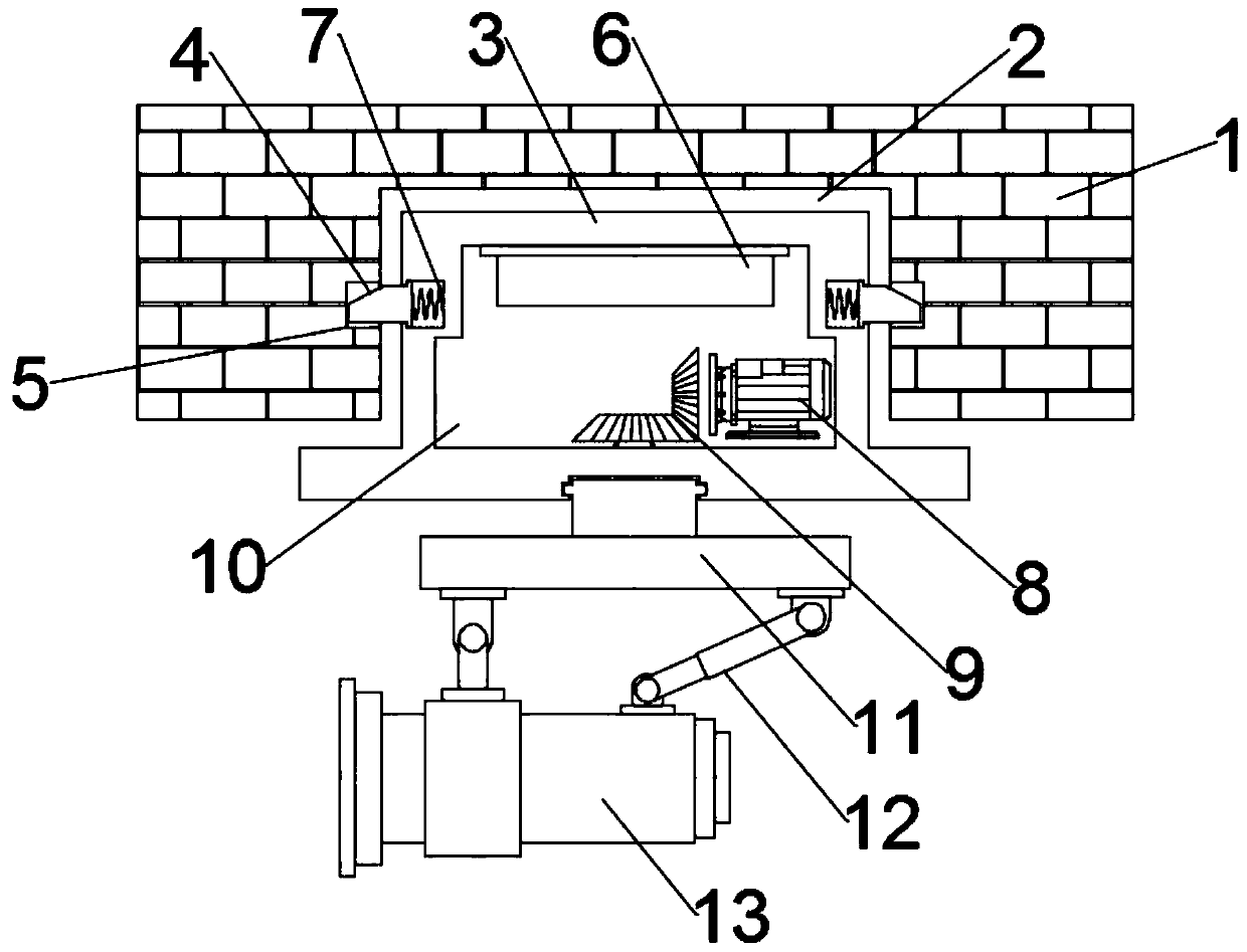
[0029] see figure 1 , in the embodiment of the present invention, a video monitoring device for security, including a mounting part 3; the mounting part 3 is embedded in the embedded groove 2 provided on the installation wall 1, and is fixed by a buckle assembly, The lower end of the mounting part 3 is rotatably equipped with a mounting plate 11 driven to rotate by the drive assembly, the lower end of the mounting plate 11 is hinged with a camera 13, and the camera 13 is also hinged on the mounting plate 11 by an electric telescopic rod 12 hinged thereto, In this way, the multi-directional acquisition and adjustment of the camera 13 is realized, and the shooting range is wide, and the mounting part 3 is fixed in the embedded groove 2 through the provided buckle assembly, which is convenient for disassembly and installation, easy to use, and convenient for subsequent maintenance. Both the cavity 6 and the electrical element cavity 6 used for containing the control system are in...
Embodiment 2
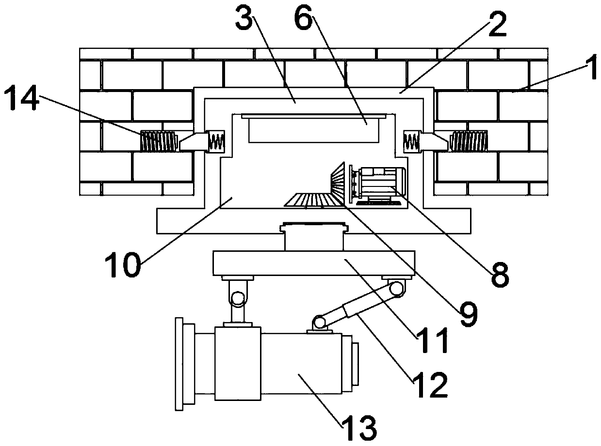
[0034] Please refer to the figure, in the embodiment of the present invention, a video monitoring device for security, including a mounting part 3; The assembly is fixed, the lower end of the mounting part 3 is rotatably installed with a mounting plate 11 driven by the drive assembly, the lower end of the mounting plate 11 is hinged with a camera 13, and the camera 13 is also hinged on the mounting plate through an electric telescopic rod 12 hinged thereto 11, so as to realize the multi-directional acquisition and adjustment of the camera 13, the shooting range is wide, and the mounting part 3 is fixed in the embedded groove 2 through the set buckle assembly, which is convenient for disassembly and installation, easy to use, and convenient for subsequent maintenance. The drive assembly and the electrical element cavity 6 for containing the control system are both installed in the placement cavity 10 provided inside the mounting part 3, so as to protect the drive assembly and th...
Embodiment 3
[0040] In the specific implementation process of the present invention, a control system is also proposed, which includes:
[0041] The collection module 100 is connected with the central processing unit 400, collects the current picture through the camera 13, and sends the picture information to the central processing unit 400;
[0042] The central processing unit 400 is used to organize the received information and issue instructions according to the type of information;
[0043] The transmission module 600 establishes a communication connection with the central processing unit 400 and the terminal device 700, and is used to transmit the information sent by the central processing unit 400 to the terminal device 700 through wireless transmission, so as to realize the display of the collection screen, wherein, the terminal Device 700 is a display device.
[0044]It also includes a sensing module 300. The sensing module 300 is used to sense the current environment. When a pede...
PUM
 Abstract
Description
Claims
Application Information
 - R&D
- Intellectual Property
- Life Sciences
- Materials
- Tech Scout
- Unparalleled Data Quality
- Higher Quality Content
- 60% Fewer Hallucinations
Browse by: Latest US Patents, China's latest patents, Technical Efficacy Thesaurus, Application Domain, Technology Topic, Popular Technical Reports.
© 2025 PatSnap. All rights reserved.Legal|Privacy policy|Modern Slavery Act Transparency Statement|Sitemap|About US| Contact US: help@patsnap.com


