
Dynamic wireless charging test device for electric vehicle

A technology for wireless charging and electric vehicles, which is applied to electric vehicles, battery circuit devices, circuit devices, etc., can solve the problems of low work efficiency, poor versatility, and time-consuming, and achieve low cost and maintenance costs, and improved The effect of testing accuracy and avoiding manual errors

Inactive Publication Date: 2019-10-11
GUILIN UNIV OF ELECTRONIC TECH
View PDF8 Cites 1 Cited by
  • Summary
  • Abstract
  • Description
  • Claims
  • Application Information

AI Technical Summary

Problems solved by technology

At present, electric vehicles have problems such as easy to cause battery pollution, poor battery life, and long single charging time, which consume a lot of time in the charging process, and there are certain safety hazards in the charging process
[0003] With the gradual popularization of wireless charging standards, two major industrial chains have been formed, the transmitting end and the receiving end. The wireless charging industry is booming. However, in terms of current testing, due to the high frequency of wireless charging, for example, 85kHz is generally used in car wireless charging. Therefore, the difficulty of the test lies in the power consumption and efficiency test. Generally, it is required to test the efficiency of the DC-DC terminal and the AC-AC efficiency of the transmitter and receiver. The DC-DC terminal is easy to test, but the difficulty lies in the efficiency test of the AC-AC terminal.
At present, according to the standard manual measurement of the place where the coil is located, the accuracy of position calibration is poor, the reproducibility of measurement is low, and the work efficiency of manual measurement is not high. There is no complete test and detection plan for dynamic wireless charging system testing, and Not very versatile

Method used


Image

  • Dynamic wireless charging test device for electric vehicle
  • Dynamic wireless charging test device for electric vehicle
  • Dynamic wireless charging test device for electric vehicle

Examples


Embodiment Construction

[0027] In order to make the objectives, technical solutions and advantages of the present invention clearer and clearer, the technical solutions in the embodiments of the present invention will be clearly and completely described below in conjunction with specific embodiments and with reference to the accompanying drawings. It should be noted that the described embodiments of the present invention are illustrative but not restrictive of the present invention, and thus the present invention is not limited to the above-described embodiments. Based on the principles of the present invention, all other implementations obtained by those skilled in the art without creative efforts are deemed to be within the protection of the present invention.

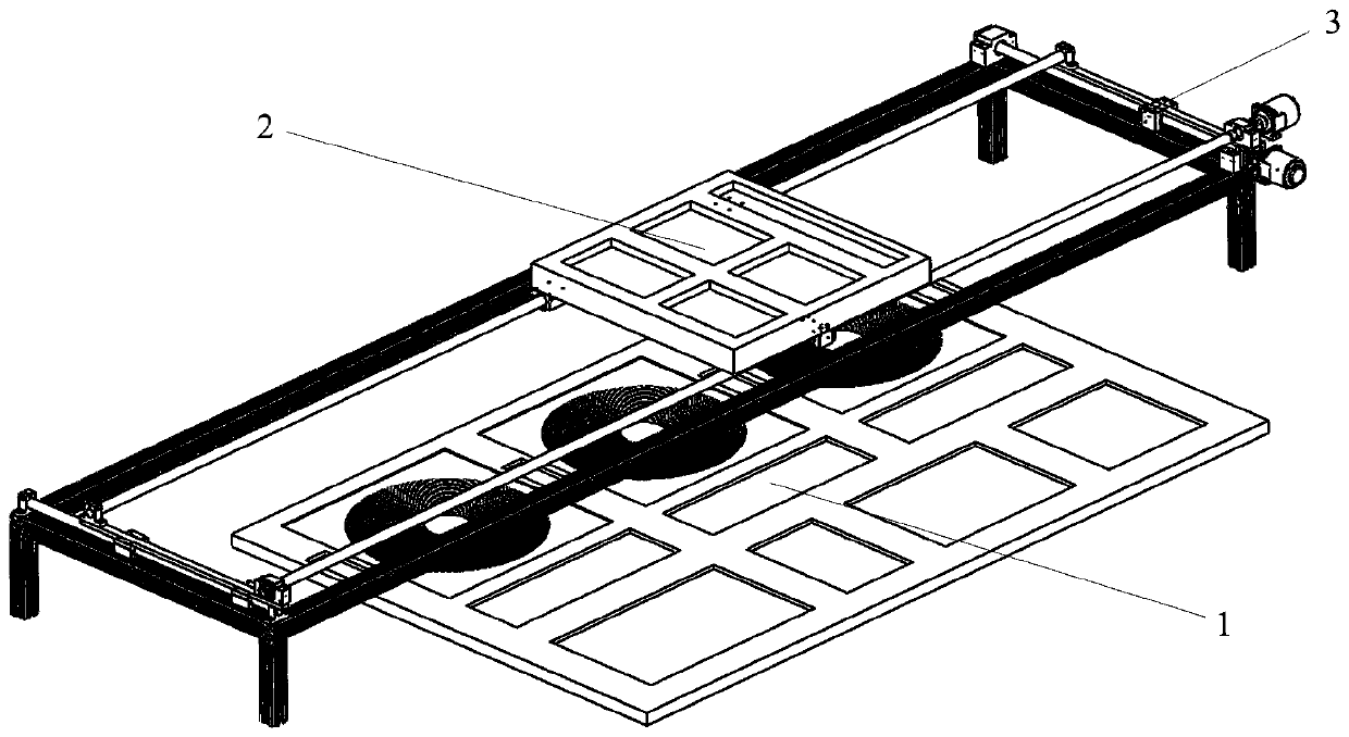
[0028] The present invention simulates the actual wireless charging condition and designs a test device. By laying transmitting coils along the road where the electric vehicle travels, when the electric vehicle travels between two adjacent t...


PUM


Abstract

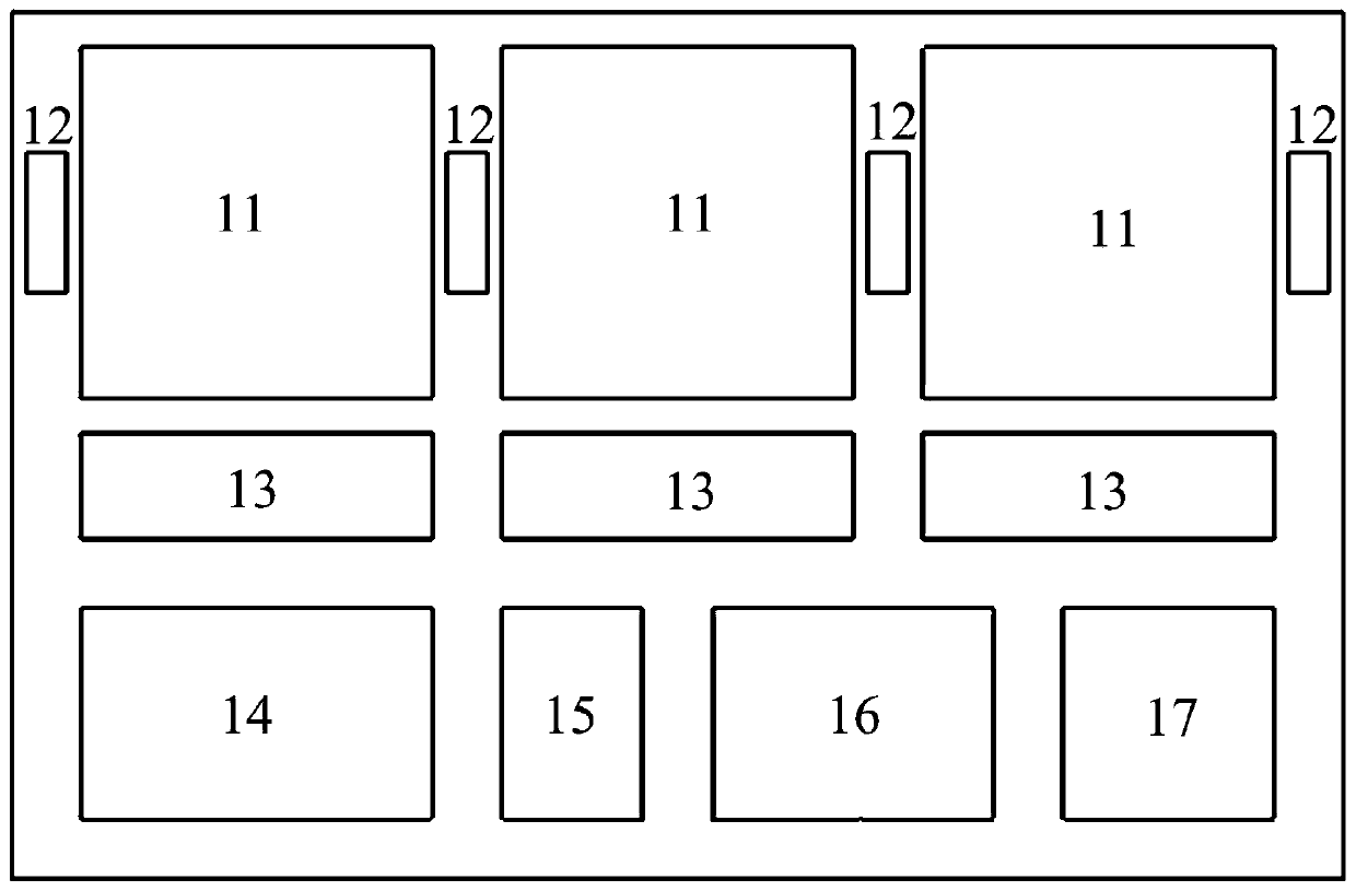
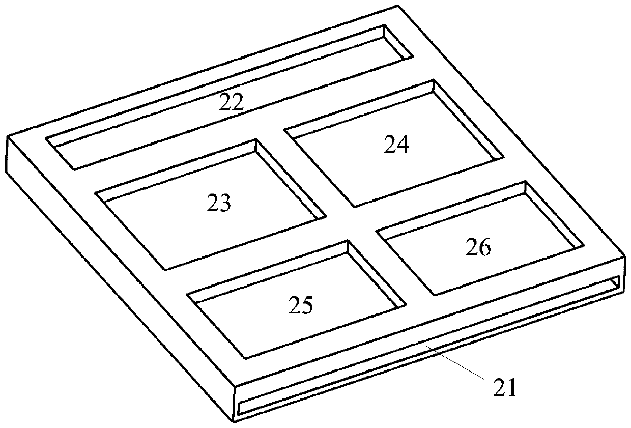
The invention discloses a dynamic wireless charging test device for an electric vehicle and belongs to the field of wireless technologies of the electric vehicle. The test device comprises a transmitting terminal mechanism, a receiving terminal mechanism and a power transmission mechanism, wherein the transmitting terminal mechanism and the power transmission mechanism are fixed on the ground; andthe receiving terminal mechanism is fixed on the power transmission mechanism. Different system properties in the wireless charging process can be tested, and a higher use rate of the device is realized. The dynamic wireless charging test device for the electric vehicle has the advantages of being efficient, safe, reliable, low in cost and maintenance charge, simple to operate, intelligent, controllable and the like.

Description

technical field [0001] The invention relates to the field of electric vehicle wireless technology, in particular to a dynamic wireless charging test device for electric vehicles. Background technique [0002] As problems such as global warming, air pollution, and the decline of petrochemical energy reserves become more and more serious, people begin to seek effective methods that can replace traditional cars and solve environmental pollution and other problems. As a new energy vehicle, electric vehicles have the advantages of low carbon, no pollution, environmental protection and cleanliness, and are an important development direction of new energy vehicles in the future. At present, electric vehicles have problems such as easy to cause battery pollution, poor battery life, and long single charging time. It takes a lot of time during the charging process, and there are certain safety hazards in the charging process. [0003] With the gradual popularization of wireless charg...

Claims


Application Information

Patent Timeline
Patent Type & Authority Applications(China)
IPC IPC(8): G01R31/00G01D21/02H02J7/02H02J50/12H02J50/30
CPCG01D21/02G01R31/00H02J7/025H02J50/12H02J50/30
Inventor 范兴明张伟杰张鑫
Owner GUILIN UNIV OF ELECTRONIC TECH
Learn More