Polarization rotator
A polarization rotator, polarization rotation technology, applied in the direction of instruments, optical waveguide light guides, light guides, etc., can solve the problem that the device is not suitable for micron-scale waveguide platforms and so on
- Summary
- Abstract
- Description
- Claims
- Application Information
AI Technical Summary
Problems solved by technology
Method used
Image
Examples
Embodiment Construction
[0049] Aspects and embodiments of the invention are discussed below with reference to the accompanying drawings. Further aspects and embodiments will be apparent to those skilled in the art. All documents mentioned herein are incorporated herein by reference.
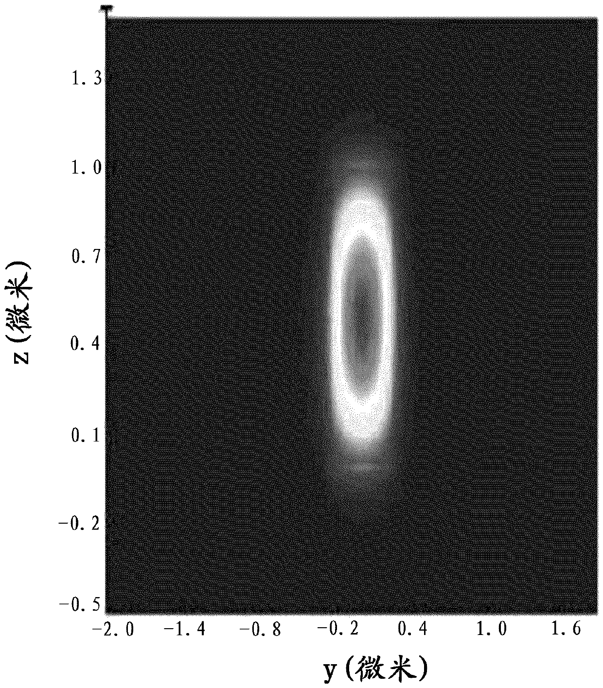
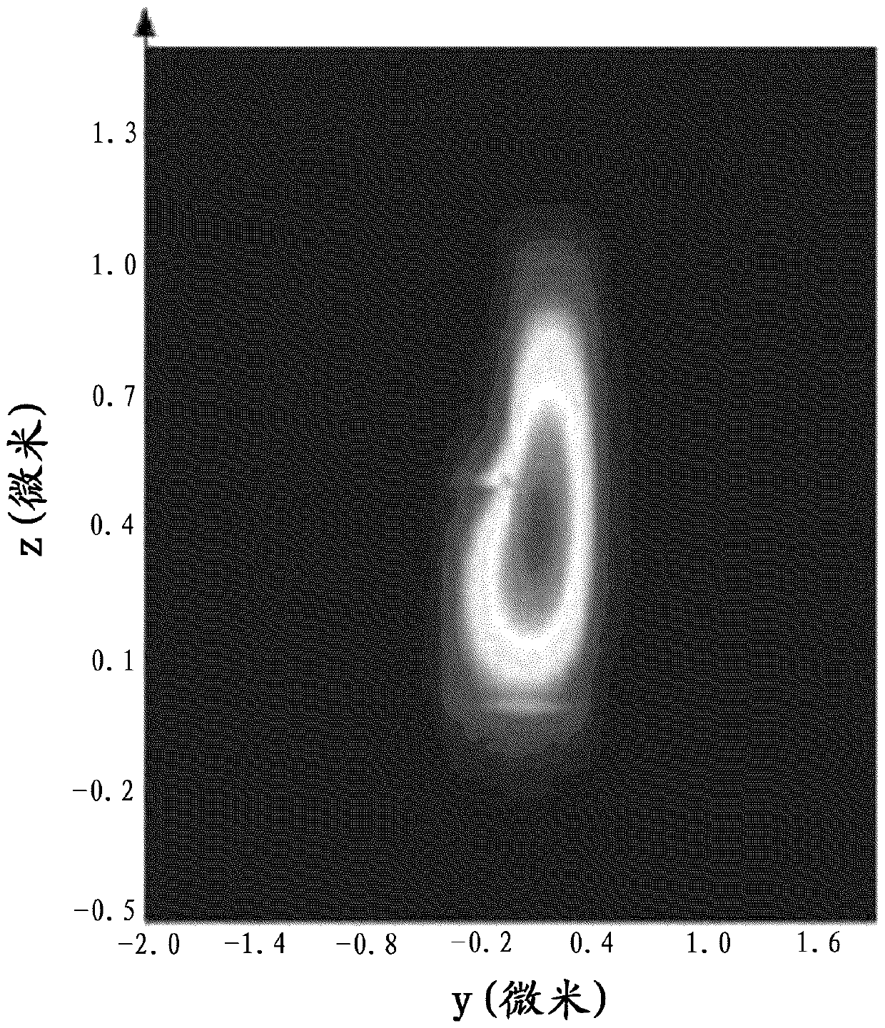
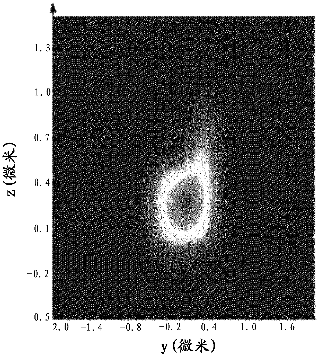
[0050] Figure 1A and Figure 1B A perspective view of a polarization rotator 100 according to the invention is shown. In general, the rotator can be regarded as comprising: an input waveguide 101 , a rib waveguide formed by a slab portion 102 and a ridge portion 103 , and an output waveguide 105 . Light entering the rotator enters an input waveguide 101 whose width shrinks until it matches the first width of the rib waveguide. As light passes through the rib waveguide, the polarization of the light is rotated from TM to TE or vice versa. The properties of rib waveguides are discussed in more detail below. Once the light has passed through the rib waveguide, the light enters the output waveguide. The width of the ...
PUM
| Property | Measurement | Unit |
|---|---|---|
| Length | aaaaa | aaaaa |
| Width | aaaaa | aaaaa |
| Width | aaaaa | aaaaa |
Abstract
Description
Claims
Application Information
 - R&D
- Intellectual Property
- Life Sciences
- Materials
- Tech Scout
- Unparalleled Data Quality
- Higher Quality Content
- 60% Fewer Hallucinations
Browse by: Latest US Patents, China's latest patents, Technical Efficacy Thesaurus, Application Domain, Technology Topic, Popular Technical Reports.
© 2025 PatSnap. All rights reserved.Legal|Privacy policy|Modern Slavery Act Transparency Statement|Sitemap|About US| Contact US: help@patsnap.com


