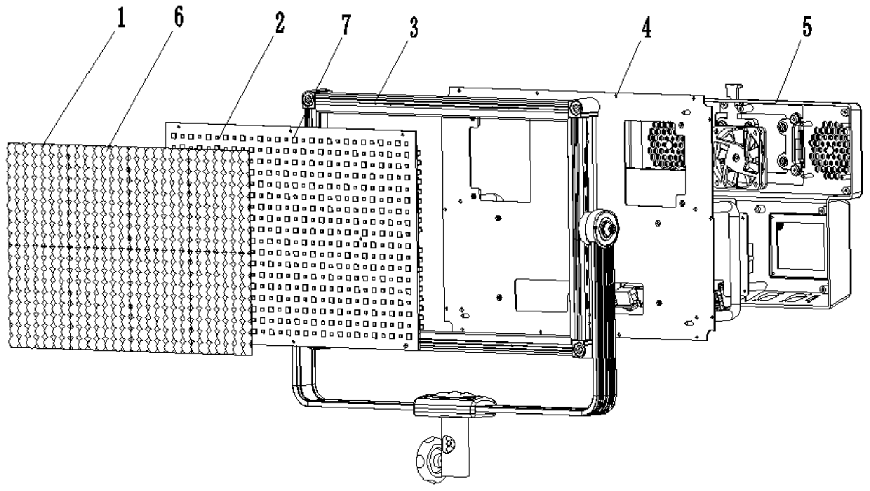
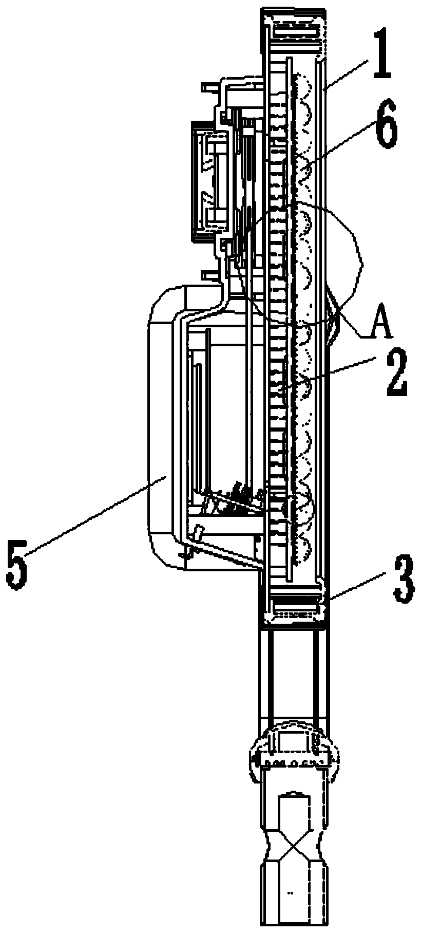
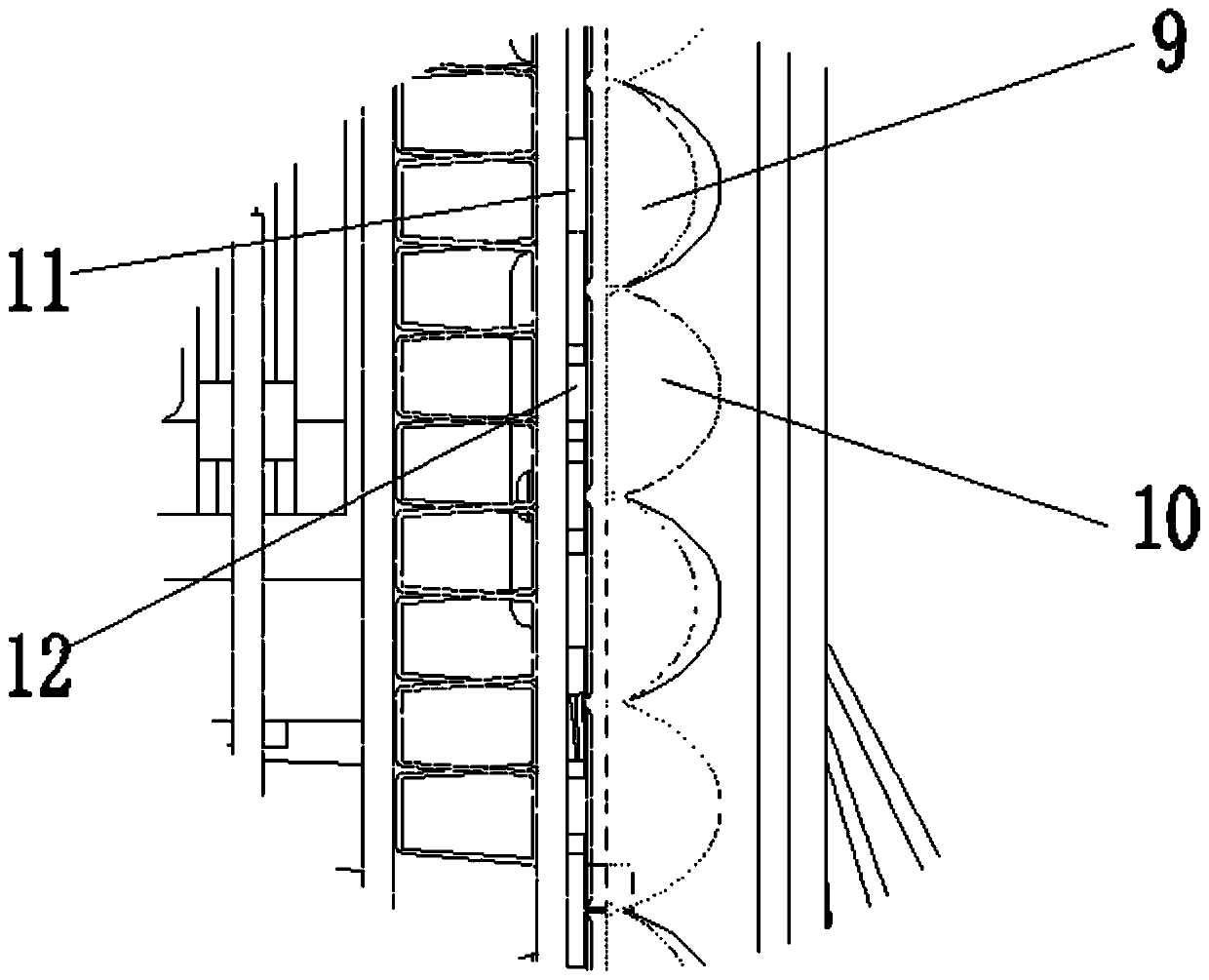
LED photography lamp with viewing angle capable of being adjusted in multiple stages

An LED photography light, multi-level adjustment technology, applied in photography, optics, instruments, etc., can solve the problem that the illumination area and brightness of the LED photography light cannot be adjusted, the distance from the optical accessories to the LED light source cannot be adjusted, and the shooting effect of the LED photography light is affected, etc. problem, to achieve the effect of adjusting the light area and brightness, easy to popularize and apply, and full of functions

Inactive Publication Date: 2019-10-11
林璧光
View PDF11 Cites 3 Cited by
  • Summary
  • Abstract
  • Description
  • Claims
  • Application Information

AI Technical Summary

Problems solved by technology

Because the optical accessories need to have a certain distance from the LED light source, the existing optical accessories only have one specification, and the distance between the optical accessories and the LED light source cannot be adjusted, resulting in the unadjustable illumination area and brightness of the LED photography light, and ultimately resulting in the inability to adjust the light output angle. Adjustment, a kind of LED video light has only one specific light emitting angle, which cannot meet the needs of multiple situations at the same time, and the application range is small, which affects the shooting effect of the LED video light

Method used


Image

  • LED photography lamp with viewing angle capable of being adjusted in multiple stages
  • LED photography lamp with viewing angle capable of being adjusted in multiple stages
  • LED photography lamp with viewing angle capable of being adjusted in multiple stages

Examples


Embodiment Construction

[0042] The technical solutions of the present invention will be clearly and completely described below in conjunction with the accompanying drawings. Apparently, the described embodiments are some of the embodiments of the present invention, but not all of them. Based on the embodiments of the present invention, all other embodiments obtained by persons of ordinary skill in the art without making creative efforts belong to the protection scope of the present invention.

[0043] In the description of the present invention, it should be noted that the terms "center", "upper", "lower", "left", "right", "vertical", "horizontal", "inner", "outer" etc. The indicated orientation or positional relationship is based on the orientation or positional relationship shown in the drawings, and is only for the convenience of describing the present invention and simplifying the description, rather than indicating or implying that the referred device or element must have a specific orientation, ...


PUM

PropertyMeasurementUnit
Beam angleaaaaaaaaaa
Heightaaaaaaaaaa
Beam angleaaaaaaaaaa

Abstract

The invention belongs to the technical field of optical equipment and particularly relates to an LED photography lamp with a viewing angle capable of being adjusted in multiple stages. The LED photography lamp comprises a shell, wherein a backboard is arranged on the back of the shell; the face of the shell is connected with a transparent cover board; optical accessories are arranged on the transparent cover board and are configured into multiple specifications; a lamp panel is arranged at one end, close to the transparent cover board, in the shell; LED light sources are arranged on the lamp panel and are configured into multiple specifications; the LED light sources and the optical accessories are oppositely arranged; and a circuit board is arranged at one end, close to the backboard, inthe shell and is connected to the LED light sources through a light source changeover switch. According to the LED photography lamp, adjustment of light-emitting angles is achieved through changing the focal distances of lens combinations of the LED photography lamp or changing the distances between lenses of the LED photography lamp and the light sources, so that adjustment of the illumination area and the brightness of the LED photography lamp is achieved and the viewing angle of the LED photography lamp is adjusted in multiple stages. The LED photography lamp is simple in structure, convenient to operate, wide in application range and good in shooting effect, and can meet the shooting requirements of different scenes.

Description

technical field [0001] The invention belongs to the technical field of optical equipment, and in particular relates to an LED photographic light whose light output angle can be adjusted in multiple steps. Background technique [0002] In recent years, with the development of micro-movies, LED photography lights have generally entered the field of photography, and their applications are becoming more and more extensive. [0003] LED photography light is a photography supplementary lighting equipment that uses LED light-emitting diodes as the light-emitting body. It can effectively solve the problem that the picture taken by a digital camera is not clear in an environment with insufficient light. It provides an appropriate auxiliary light source for shooting subjects such as digital cameras, solves the limitations of digital cameras limited by light, and can effectively expand the use range of digital cameras. [0004] Existing LED photography lights generally include a back...

Claims


Application Information

Patent Timeline
IPC IPC(8): G03B15/02
CPCG03B15/02
Inventor 林璧光
Owner 林璧光
Why Eureka
Try Eureka