
Optical camera angle calibration method, device and equipment, and storage medium

An optical camera and angle technology, applied in the field of satellite photogrammetry, can solve problems such as poor timeliness and difficulty in obtaining

Active Publication Date: 2021-05-07
中国人民解放军61540部队 +1
View PDF8 Cites 0 Cited by
  • Summary
  • Abstract
  • Description
  • Claims
  • Application Information

AI Technical Summary

Problems solved by technology

However, when the on-orbit calibration method based on the test site is used to measure the variation of the main optical axis angle of the optical camera, due to the satellite overhead cycle and weather conditions, it is difficult to obtain a complete test site image, and the timeliness is poor.

Method used


Image

  • Optical camera angle calibration method, device and equipment, and storage medium
  • Optical camera angle calibration method, device and equipment, and storage medium
  • Optical camera angle calibration method, device and equipment, and storage medium

Examples


Embodiment Construction

[0048] Various exemplary embodiments, features, and aspects of the present disclosure will be described in detail below with reference to the accompanying drawings. The same reference numbers in the figures indicate functionally identical or similar elements. While various aspects of the embodiments are shown in drawings, the drawings are not necessarily drawn to scale unless specifically indicated.

[0049] The word "exemplary" is used exclusively herein to mean "serving as an example, embodiment, or illustration." Any embodiment described herein as "exemplary" is not necessarily to be construed as superior or better than other embodiments.

[0050] In addition, in order to better illustrate the present disclosure, numerous specific details are given in the following specific implementation manners. It will be understood by those skilled in the art that the present disclosure may be practiced without some of the specific details. In some instances, methods, means, components...


PUM


Abstract

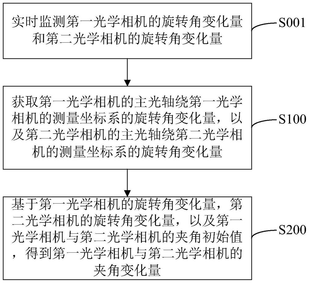
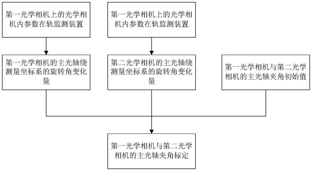
The present application relates to an optical camera angle calibration method, device and equipment, and a storage medium, wherein the method includes: obtaining the amount of rotation angle variation of the main optical axis of the first optical camera around the measurement coordinate system of the first optical camera, and the second The main optical axis of the second optical camera is around the rotation angle variation of the measurement coordinate system of the second optical camera; based on the rotation angle variation of the first optical camera, the rotation angle variation of the second optical camera, and the relationship between the first optical camera and the second optical camera The initial value of the included angle of the two optical cameras is used to obtain the change amount of the included angle between the first optical camera and the second optical camera. Compared with the calibration method based on the test field in the related art, the optical camera angle calibration method in the embodiment of the present disclosure does not need to rely on the acquisition cycle of the test field image, thus effectively shortening the calibration cycle and improving Calibration accuracy, and ultimately improve the calibration effect.

Description

technical field [0001] The present disclosure relates to the technical field of satellite photogrammetry, and in particular to a method, device and equipment for calibrating an included angle of an optical camera, and a storage medium. Background technique [0002] In non-control point satellite photogrammetry, the angle change between the main optical axes of optical cameras is one of the key factors affecting the accuracy of satellite positioning. Therefore, only by calibrating the included angle of the main optical axis of the optical camera as accurately as possible can the positioning accuracy be improved. Before the satellite is launched, the initial value of the angle between the main optical axis of the optical camera is determined by the method of laboratory calibration. Among them, when the satellite is in orbit, affected by various complex factors, the main optical axis of the optical camera will undergo changes such as thermoelastic deformation, resulting in som...

Claims


Application Information

Patent Timeline
Patent Type & Authority Patents(China)
IPC IPC(8): G06T7/80
CPCG06T7/80
Inventor 刘薇蒋唯娇钱方明王慧王柯俨
Owner 中国人民解放军61540部队
Learn More