Power saving control apparatus and power saving control method applied to display driving circuit

A control device and display drive technology, applied in the direction of static indicators, electrical digital data processing, instruments, etc., can solve the problems of power waste and power waste that cannot be independently improved, and achieve the effect of reducing data storage

Active Publication Date: 2019-10-11
RAYDIUM SEMICON
View PDF13 Cites 0 Cited by
  • Summary
  • Abstract
  • Description
  • Claims
  • Application Information

AI Technical Summary

Problems solved by technology

However, when the slew rate is also fixed, the resulting time TD is also fixed, thus causing unnecessary waste of power
[0004] In order to improve the above shortcomings, the current method needs to compare the previous data latch (Previous data latch) PLA and the current data latch (Display data latch) DLA through the comparator COM in the timing controller (Timing controller) TCON. Stored data, and then dynamically adjust the bias voltage and slew rate of the bias control units (Bias control unit) BCU1 ~ BCUN ​​in each source driver (Source driver) SD1 ~ SDN according to the comparison result, that is, the source driver still cannot Independently improve this unnecessary power waste

Method used


Image

  • Power saving control apparatus and power saving control method applied to display driving circuit
  • Power saving control apparatus and power saving control method applied to display driving circuit
  • Power saving control apparatus and power saving control method applied to display driving circuit

Examples


Embodiment Construction

[0084] A specific embodiment according to the present invention is a power saving control device. In this embodiment, the power saving control device is applied to the display driving circuit, and the display driving circuit can be a source driver and the source driver is coupled to the timing controller, or the display driving circuit is a source driver embedded with a timing controller , but not limited to this.

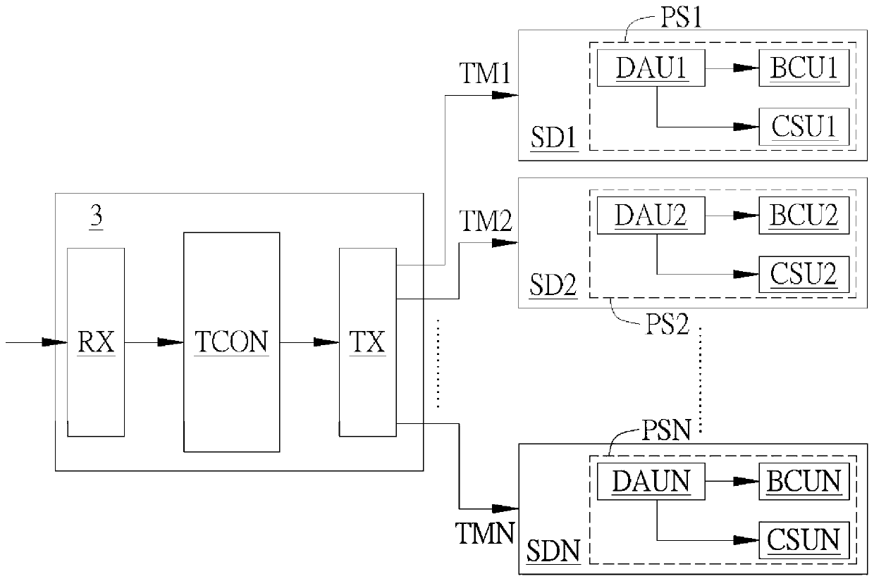
[0085] Please refer to Figure 3A , Figure 3A For this purpose, the schematic diagram of the power saving control device in the embodiment applied to the source driver.

[0086] Such as Figure 3A As shown, the timing controller 3 is respectively coupled to N source drivers SD1˜SDN, where N is a positive integer. The timing controller 3 includes a receiving unit RX, a timing control unit TCON and a transmitting unit TX. The receiving unit RX is coupled to the timing control unit TCON. The timing control unit TCON is coupled to the transmission unit TX. The ...


PUM


Abstract

A power saving control apparatus and a power saving control method applied to a display driving circuit are disclosed. The power saving control apparatus includes a data analysis unit, a bias controlunit and a charge sharing unit. The data analysis unit is coupled to the bias control unit and the charge sharing unit respectively. The data analysis unit instantly analyzes the display data to generate an instant analysis result and dynamically adjust the setting of bias and slew rate of the bias control unit according to the instant analysis result. Different channels can select the same setting or different settings. The data analysis unit can dynamically adjust the setting of charge sharing range and charge sharing group number needed to be performed by the charge sharing unit according to the instant analysis result, thus achieving the optimal power saving effect.

Description

technical field [0001] The present invention is related to the display, in particular to a power saving control device and a power saving control method applied to a display driving circuit. Background technique [0002] Generally speaking, the traditional bias control method adopts a bias control circuit with a fixed slew rate and bias voltage, regardless of the variation of the actual output voltage, resulting in unnecessary waste of power. [0003] For example, if figure 1 As shown in the output voltage characteristic diagram, if the required time TD is used to meet the output voltage of the higher voltage level V1, its slope is G1; once the output voltage changes to the lower voltage level V2, the bias voltage is fixed and cannot change, so the slope G2 will be equal to G1, and the actual required time should be less than the time TD. However, in the case that the slew rate is also fixed, the time TD is also fixed, thus causing unnecessary waste of power. [0004] In ...

Claims


Application Information

Patent Timeline
Patent Type & Authority Applications(China)
IPC IPC(8): G09G3/20
CPCG09G3/20G09G2330/021G06F1/3265G06F1/3296G06F1/3218G09G3/3688G09G2310/0248G09G2360/16G09G2360/127Y02D10/00G09G2310/08
Inventor 陈建豪吴智豪黄智全陈松伯
Owner RAYDIUM SEMICON
Why Eureka
Try Eureka