Switch cabinet

A switchgear and side panel technology, applied in the field of switchgear, can solve the problems of great effort, labor consumption, and only the whole cabinet can be transported, and achieve the effects of reasonable space utilization, convenient operation and maintenance, and improved stability.

Active Publication Date: 2019-10-11
浙江巨高电力设备有限公司
View PDF8 Cites 6 Cited by
  • Summary
  • Abstract
  • Description
  • Claims
  • Application Information

AI Technical Summary

Problems solved by technology

However, the volume and quality of the integrated switchgear are large, and the workers can only carry the whole cabinet when transferring. Therefore, the workers need to spend a lot of energy every time the switchgear is moved, which needs to be improved.

Method used


Image

  • Switch cabinet
  • Switch cabinet
  • Switch cabinet

Examples


Embodiment Construction

[0035] The present invention will be described in further detail below in conjunction with the accompanying drawings.

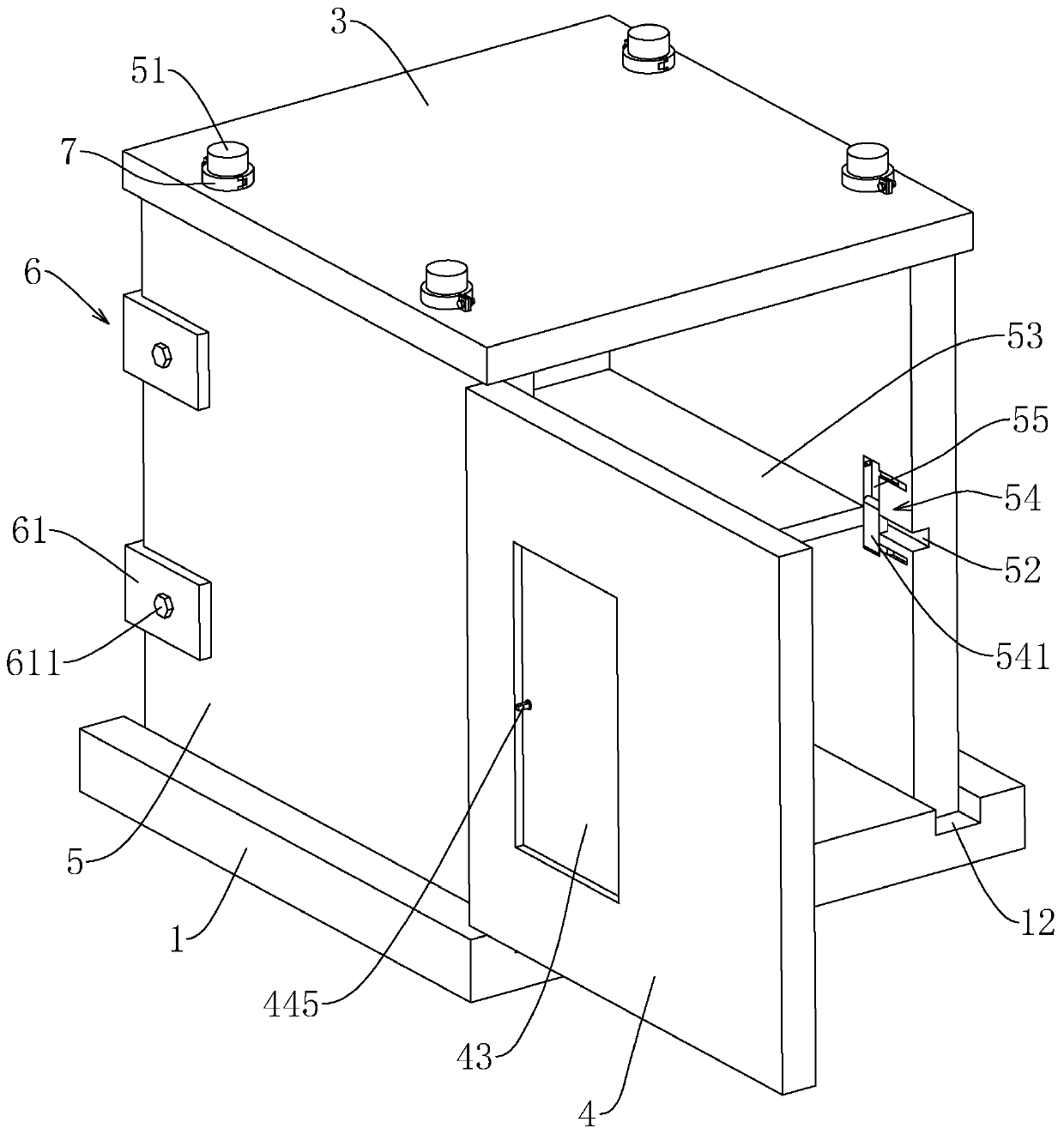
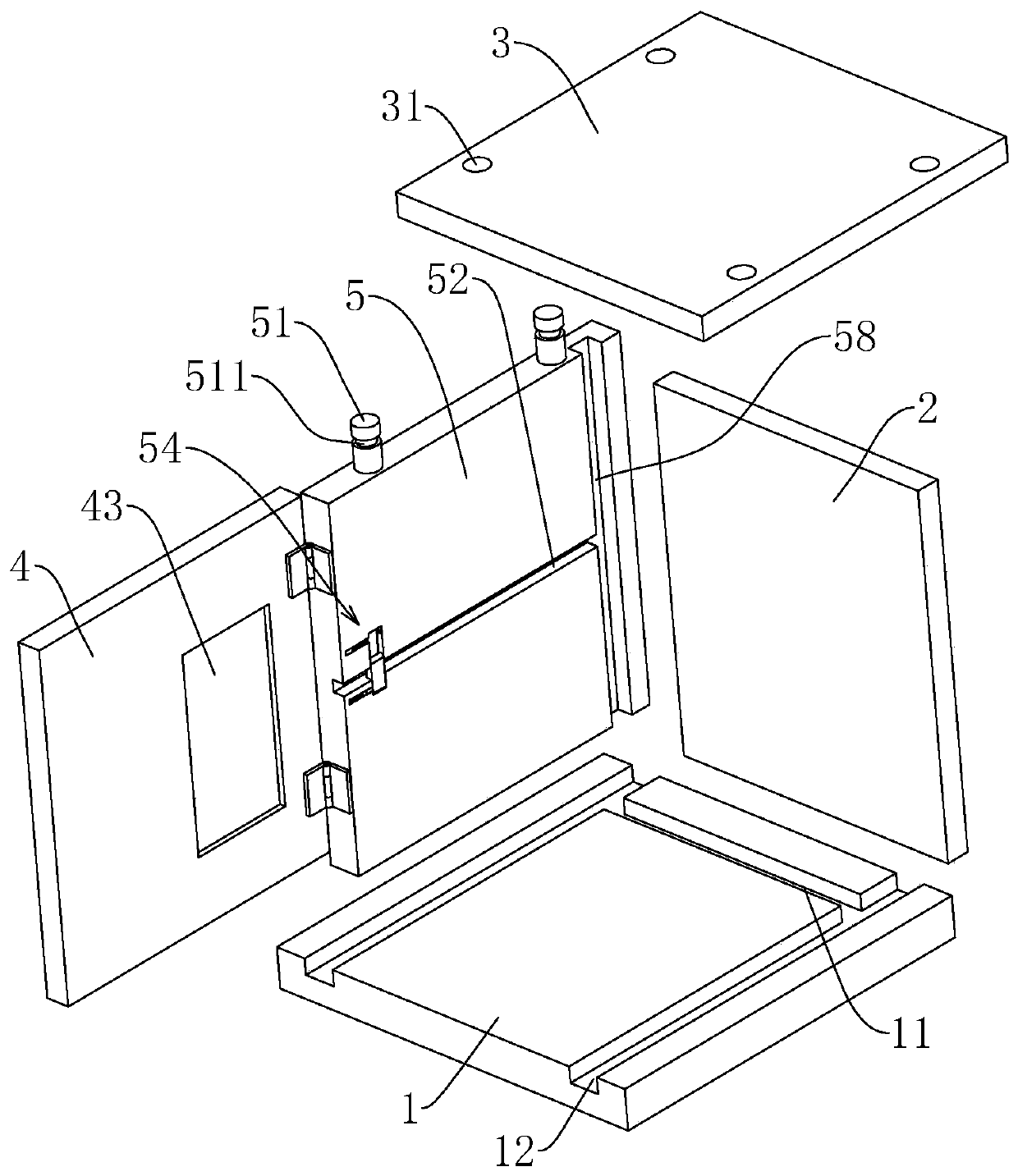
[0036] This embodiment discloses a switch cabinet, such as figure 1 , figure 2 As shown, it includes a base plate 1, a back plate 2, a top plate 3, a door plate 4 and two side plates 5. The upper end surface of the base plate 1 is provided with a positioning groove 11 and two parallel installation grooves 12, and the two installation grooves 12 are respectively close to The left and right ends of the bottom plate 1 and the positioning groove 11 are close to the rear end of the bottom plate 1 and are perpendicular to the installation groove 12 . The lower ends of the two side plates 5 are respectively placed in the two installation grooves 12 , and the lower ends of the back plate 2 are placed in the positioning grooves 11 , and the back plate 2 and the two side plates 5 are connected by two sets of fasteners 6 . The top board 3 is located directly above th...


PUM


Abstract

The invention relates to the technical field of electronic equipment, and discloses a switch cabinet. The key point of the technical scheme is as follows: the switch cabinet comprises a bottom plate,a back plate, a top plate, a door plate and two side plates; a positioning slot and two mutually parallel installation slots are formed in the base plate; the lower ends of the two side plates are separately inserted into the two installation slots; the lower end of the back plate is inserted into the positioning slot; fixing slots are formed in end faces, close to each other, of the two side plates; two ends of the back plate are separately positioned in the two fixing slots; the back plate is connected with the adjacent side plate via a fastener; the top plate is fixed on the back plate andthe upper sides of the side plates via installation pieces; the door plate is hinged to one of the side plates via a hinge; multiple partition slots extending along the length direction are formed inend faces, close to each other, of the two side plates; a partition plate is inserted between any two partition slots with the same height; and the side plate is provided with a limiting piece for limiting the separation of the partition plate and the side plate. The switch cabinet provided by the invention has the effect of being more labor-saving when in transportation.

Description

technical field [0001] The present invention relates to the technical field of electric equipment, more specifically it relates to a switchgear. Background technique [0002] Switchgear is a kind of electrical equipment, whose main function is to open and close, control and protect electrical equipment during the process of power generation, transmission, distribution and power conversion in the power system. The external line of the switch cabinet first enters the main control switch in the cabinet, and then enters the sub-control switch. Each branch is set according to its needs, such as instrumentation, automatic control, motor magnetic switch, various AC contactors, etc. [0003] The traditional switchgear is usually a one-piece structure. After the switchgear is processed and produced at different stations, it needs to be transported to the designated location by hydraulic truck or flatbed truck. During transportation, at least four workers are required to lift the swi...

Claims


Application Information

Patent Timeline
Patent Type & Authority Applications(China)
IPC IPC(8): H02B1/30
CPCH02B1/301
Inventor 徐世伟
Owner 浙江巨高电力设备有限公司
Why Eureka
Try Eureka