Supercharge Your Innovation With Domain-Expert AI Agents!

Optical communication network receiver

An optical communication network and receiver technology, applied in the field of communication, can solve the problems such as the limitation of the angle and distance of the optical link and the inability to achieve, and achieve the effect of signal reception.

Active Publication Date: 2019-10-11
深圳市莱法照明通信科技有限公司
View PDF5 Cites 1 Cited by
  • Summary
  • Abstract
  • Description
  • Claims
  • Application Information

AI Technical Summary

Problems solved by technology

[0004] The main purpose of the present invention is to provide an optical communication network receiver that can not only increase the receiving angle but also realize long-distance reception, which is used to solve the problem of the optical link realization angle and distance of the optical communication network receiver in the prior art. limitations, technical problems that cannot achieve both

Method used


Image

  • Optical communication network receiver
  • Optical communication network receiver
  • Optical communication network receiver

Examples


Embodiment Construction

[0016] In order to enable those skilled in the art to better understand the solutions of the present invention, the following will clearly and completely describe the technical solutions in the embodiments of the present invention in conjunction with the drawings in the embodiments of the present invention. Obviously, the described embodiments are only An embodiment that is a part of the invention, not an embodiment of the same. Based on the embodiments of the present invention, all other embodiments obtained by persons of ordinary skill in the art without making creative efforts shall fall within the protection scope of the present invention.

[0017] The terms "first", "second" and the like in the description and claims of the present invention and the above drawings are used to distinguish different objects, rather than to describe a specific order. Furthermore, the terms "include" and "have", as well as any variations thereof, are intended to cover a non-exclusive inclusio...


PUM


Abstract

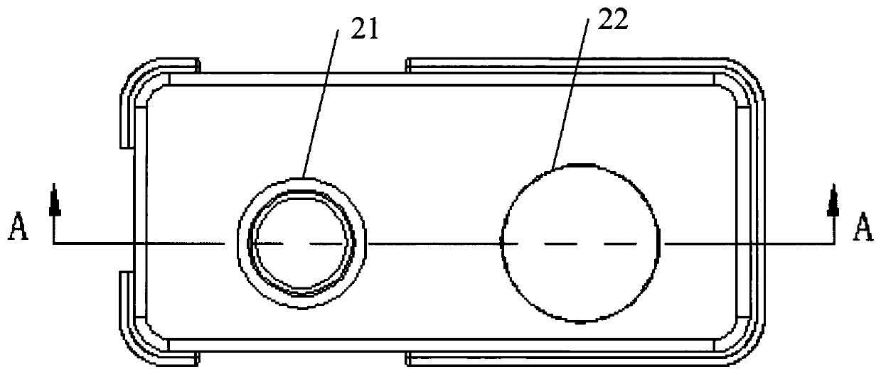
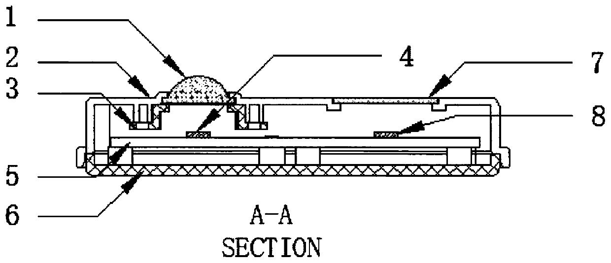
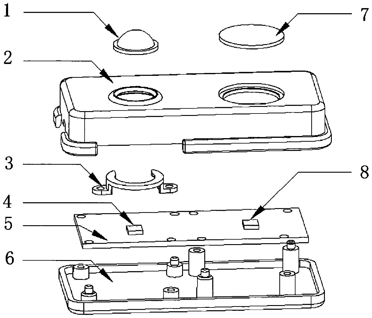
The invention discloses an optical communication network receiver comprising a main body, a long-distance receiving assembly and a large-angle receiving assembly, wherein the long-distance receiving assembly and the large-angle receiving assembly are installed on the main body. The long-distance receiving assembly comprises a convex lens installed on the surface of the main body and a first photodiode installed in the main body, and the first photodiode is located at the focus position of the convex lens. The large-angle receiving assembly comprises a planar light-transmitting device installedon the surface of the main body and a second photodiode installed in the main body, the second photodiode is located at the position of the central axis of the planar light-transmitting device, and the second photodiode is smaller than the planar light-transmitting device. The receiver provided by the invention solves the problem that the realization of the optical link of the existing optical communication network receiver is limited by the angle and the distance, and not only can carry out long-distance signal receiving, but also can carry out large-angle signal receiving.

Description

technical field [0001] The present invention relates to the field of communication technologies, in particular to a visible light wireless communication (English full name: Light Fidelity, abbreviated: LiFi) signal receiving technology, and in particular to an optical communication network receiver. Background technique [0002] In recent years, light-emitting diode (Light-Emitting Diode, LED) lighting technology has developed rapidly. Compared with traditional lighting sources, white LEDs not only have low power consumption, long service life, small size, environmental protection, but also have the advantages of good modulation performance and high response sensitivity. Utilizing this characteristic of LED, it can be used as lighting, and at the same time, it can modulate the network signal to the visible light beam of LED for data transmission, realizing an emerging visible light wireless communication (LiFi) technology. [0003] Optical communication network receiver is ...

Claims


Application Information

Patent Timeline
Patent Type & Authority Applications(China)
IPC IPC(8): H04B10/116H04B10/67
CPCH04B10/116H04B10/67
Inventor 白勃谢浩浩李柏林王昭诚赵春峰
Owner 深圳市莱法照明通信科技有限公司
Features
  • R&D
  • Intellectual Property
  • Life Sciences
  • Materials
  • Tech Scout
  • Unparalleled Data Quality
  • Higher Quality Content
  • 60% Fewer Hallucinations
Learn More