Signal receiving circuit of electronic detonator

A signal receiving and electronic detonator technology, applied in fuzes, electrical components, weapon accessories, etc., can solve problems such as inability to meet full-cycle application requirements, insufficient compatibility and stability, complex structure of receiving circuits, etc., to meet full-cycle communication requirements, elimination of channel imperfections, and the effect of meeting low-voltage and high-voltage communication requirements

Active Publication Date: 2018-10-26
NO 54 INST OF CHINA ELECTRONICS SCI & TECH GRP
View PDF4 Cites 0 Cited by
  • Summary
  • Abstract
  • Description
  • Claims
  • Application Information

AI Technical Summary

Problems solved by technology

[0005] However, the existing receiving circuit either has a complex structure resulting in high cost and power consumption, or is insufficient in compatibility and stability to meet the full-cycle application requirements

Method used


Image

  • Signal receiving circuit of electronic detonator
  • Signal receiving circuit of electronic detonator
  • Signal receiving circuit of electronic detonator

Examples


Embodiment Construction

[0021] In order to make it easier for those skilled in the art to understand the technical solution of this patent, and at the same time, in order to make the technical purpose, technical solution and beneficial effect of this patent clearer, and to fully support the protection scope of the claims, the following is a specific case in the form of this patent. The technical solution of the patent makes further and more detailed descriptions.

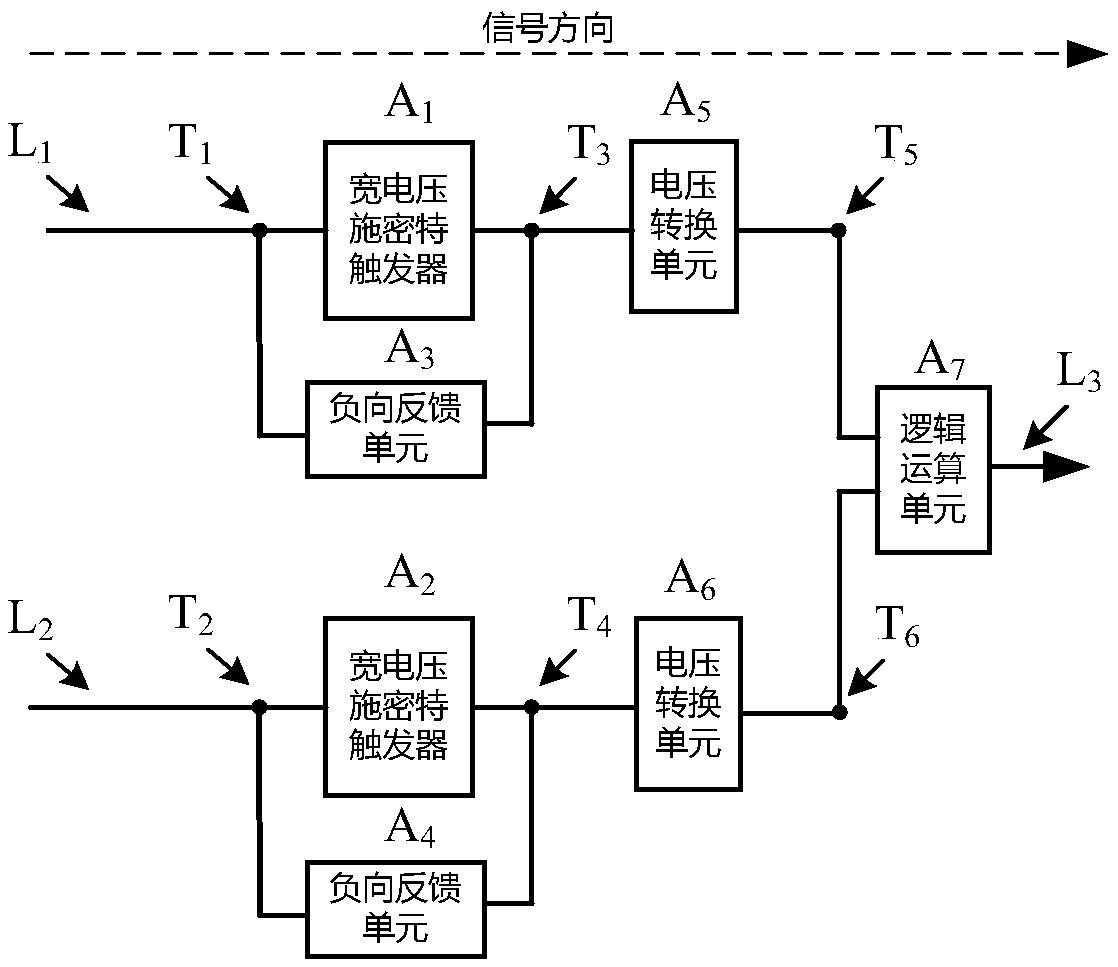
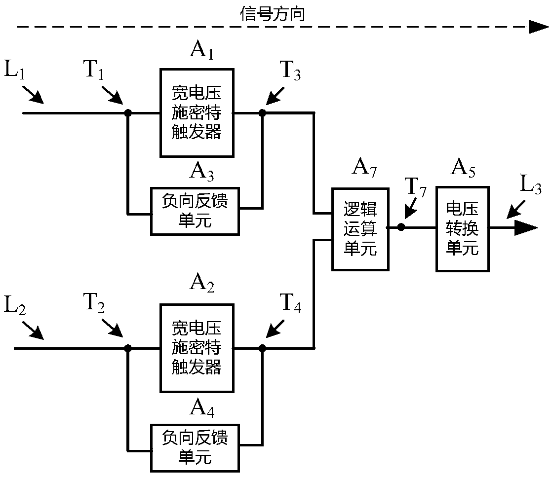
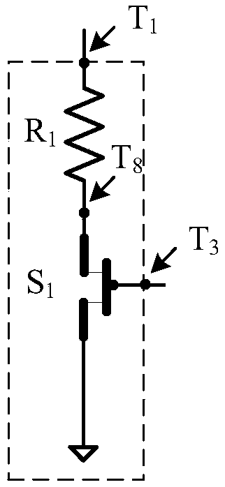
[0022] An electronic detonator signal receiving circuit, which includes a logic operation unit and two signal receiving paths, the logic operation unit has two input ends and an output end, the two signal receiving paths and the two signal receiving paths of the logic operation unit The input terminals are connected one by one, and each signal receiving path includes a Schmitt trigger with a working voltage of 2.5V to 24V and a voltage conversion unit for converting the input level signal into a standard level signal output, The standard l...


PUM


Abstract

The invention discloses a signal receiving circuit of an electronic detonator, and belongs to the technical field of electronic detonators. The signal receiving circuit comprises a logical operation unit and two signal receiving accesses, the logical operation unit has two input ends and one output end, and the two signal receiving accesses are connected with the two input ends of the logical operation unit in a manner of one-to-one correspondence. Each signal receiving access comprises a Schmidt trigger with operating voltage of 2.5V-24V and a voltage converting unit used for converting inputlevel signals to reference level signals for output, and the Schmidt triggers, the voltage converting units and the logical operation unit are connected sequentially in the signal direction. The signal receiving circuit is simple in circuit structure, low in cost and power dissipation and high in reliability, can receive complex bus signals stably and correctly, and is compatible with signal transmission of low-voltage and high-voltage communication and suitable for communication between controllers and electronic detonators in processes such as production, detection and use.

Description

technical field [0001] The invention relates to the technical field of electronic detonators and pyrotechnics, in particular to an electronic detonator signal receiving circuit. Background technique [0002] The electronic detonator produced by the combination of integrated circuit technology and pyrotechnics technology is an inevitable development trend of industrial detonators. Electronic detonators use integrated circuits to replace the delayed gunpowder in industrial detonators, and use integrated circuits to achieve high-precision delay, safety control and reliable detonation. [0003] The electronic detonator is mainly composed of a circuit board, a bridge wire with a charge head, and a gunpowder tube (or a tube without detonating powder), among which the integrated circuit, additional electronic components and bridge wires are all welded on the circuit board. During use, the controller supplies power and communicates with the electronic detonator through the bus, t...

Claims


Application Information

Patent Timeline
Patent Type & Authority Applications(China)
IPC IPC(8): F42C19/00H04B1/16
CPCF42C19/00H04B1/16
Inventor 张晓峰刘言赵晓龙甘伟李哲许仕龙
Owner NO 54 INST OF CHINA ELECTRONICS SCI & TECH GRP
Why Eureka
Try Eureka