Spraying equipment for large pipe inner side

A technology for spraying equipment and pipes, applied in the field of spraying equipment inside large pipes, can solve the problems of operator's health injury, low spraying efficiency, large workload, etc., to improve applicability and stability, improve spraying efficiency and effect, The effect of reducing labor requirements

Inactive Publication Date: 2019-10-15
YANCHENG DONGFANG TIANCHENG MACHINERY
View PDF11 Cites 5 Cited by
  • Summary
  • Abstract
  • Description
  • Claims
  • Application Information

AI Technical Summary

Problems solved by technology

[0002] Pipe is the material used to make pipe fittings. Different pipes use different pipes. The quality of pipes directly determines the quality and service life of pipes. With the development of society, a large number of pipes are used in construction projects, power plants, and chemical plants. And many other fields, and the pipe needs to go through multiple processing procedures before it can reach the use standard, and spraying paint, corrosion-resistant paint and other liquid agents greatly affect the service life of the pipe
[0003] The existing spraying method is generally that the operator sprays with a hand-held spraying equipment, and the spraying distance, angle, thickness and other values ​​cannot be fixed, resulting in low spraying efficiency, uneven spraying, affecting the quality and service life of the pipe, and the workload is high. Large, it is easy to cause fatigue of the operators. During the spraying process, due to the need for manual construction, the spraying liquid is easily inhaled into the lungs of the operators, causing harm to the health of the operators. Therefore, the present invention designs a large-scale pipe inner spraying equipment To solve the problems existing in the prior art

Method used


Image

  • Spraying equipment for large pipe inner side
  • Spraying equipment for large pipe inner side
  • Spraying equipment for large pipe inner side

Examples


Embodiment Construction

[0017] The following will clearly and completely describe the technical solutions in the embodiments of the present invention with reference to the accompanying drawings in the embodiments of the present invention. Obviously, the described embodiments are only some, not all, embodiments of the present invention. Based on the embodiments of the present invention, all other embodiments obtained by persons of ordinary skill in the art without making creative efforts belong to the protection scope of the present invention.

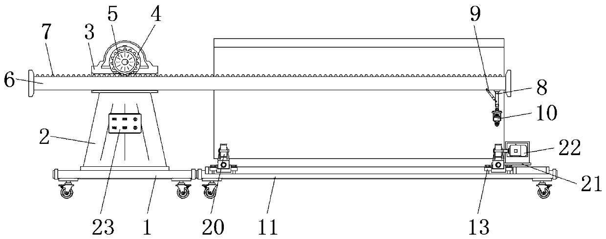
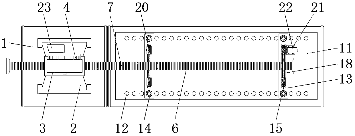
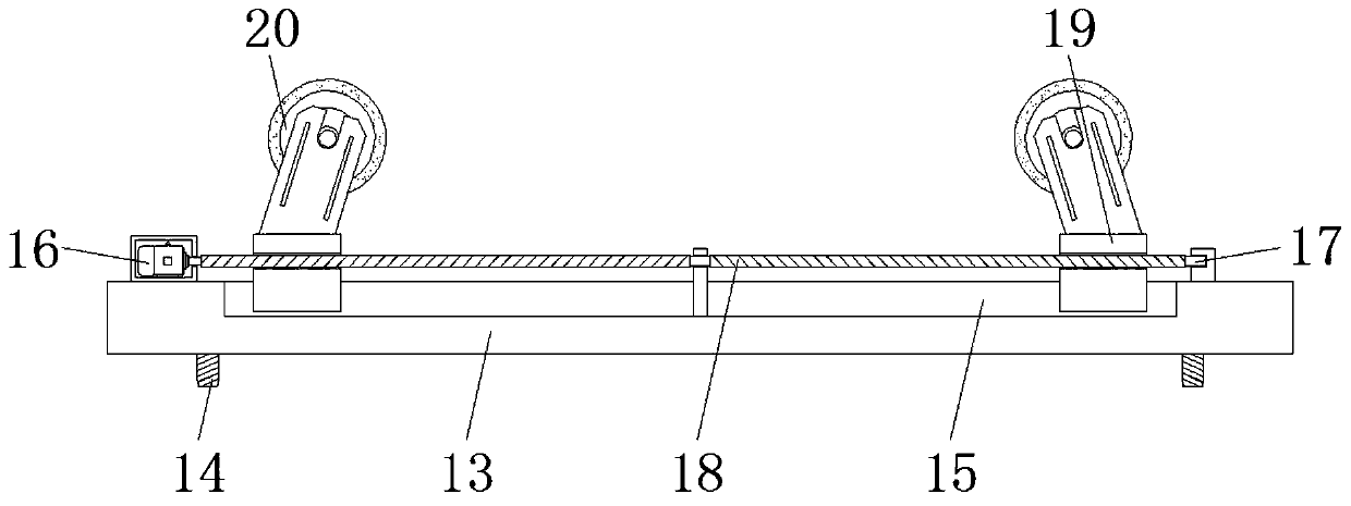
[0018] see Figure 1-3 , an embodiment provided by the present invention: a large pipe inner side spraying equipment, including a base A1, a support column 2 is installed on the top of the base A1, and a transmission chamber 3 is installed on the top of the support column 2, and one side of the transmission chamber 3 A driving motor 4 is installed, the model of the driving motor 4 is Y90S-2, and the output end of the driving motor 4 extends to the inside of th...


PUM


Abstract

The invention discloses spraying equipment for large pipe inner side. The spraying equipment comprises a base A, wherein a support column is mounted on the top of the base A, and a transmission bin ismounted on the top of the support column; a driving motor is mounted on one side of the transmission bin, and an output end of the driving motor extends into the inner side of the transmission bin; agear is mounted on the output end of the driving motor; a support arm in sliding connection with the transmission bin is arranged on the inner side of the transmission bin; and the top of the supportarm is uniformly provided with tooth grooves. According to the equipment, a connecting plate and a stepping motor B are mounted on the equipment, a pipe is controlled to continuously rotate at a constant speed in the spraying process, automatic spraying is achieved, the spraying efficiency and effect are improved, the manual requirement is reduced, and the gap between two groups of mounting plates is adjusted by adjusting the position relation of a fastening bolt and a threaded hole, so that the equipment is suitable for pipes with different lengths, and the applicability of the equipment isfurther improved.

Description

technical field [0001] The invention relates to the technical field of pipe processing equipment, in particular to a large pipe inner spraying equipment. Background technique [0002] Pipe is the material used to make pipe fittings. Different pipes use different pipes. The quality of pipes directly determines the quality and service life of pipes. With the development of society, a large number of pipes are used in construction projects, power plants, and chemical plants. And other fields, and the pipe needs to go through multiple processing procedures before it can reach the use standard, and spraying paint, corrosion-resistant paint and other liquid agents greatly affect the service life of the pipe. [0003] The existing spraying method is generally that the operator sprays with a hand-held spraying equipment, and the spraying distance, angle, thickness and other values ​​cannot be fixed, resulting in low spraying efficiency, uneven spraying, affecting the quality and ser...

Claims


Application Information

Patent Timeline
IPC IPC(8): B05B13/02B05B13/06
CPCB05B13/0228B05B13/0654
Inventor 邢礼宏
Owner YANCHENG DONGFANG TIANCHENG MACHINERY
Why Eureka
Try Eureka