
Continuous stamping robot

A technology of robots and robotic arms, applied in the field of continuous stamping robots, can solve the problems of burrs, difficult to popularize and apply, and small working range.

Inactive Publication Date: 2019-10-15
张晓卫
View PDF9 Cites 0 Cited by
  • Summary
  • Abstract
  • Description
  • Claims
  • Application Information

AI Technical Summary

Problems solved by technology

[0002] At present, stamping is a forming processing method that relies on presses and molds to apply external forces to plates, strips, pipes, and profiles to cause plastic deformation or separation, thereby obtaining workpieces of required shape and size. Existing stamping robots There are many kinds of different design concepts, and strive to meet the needs of different users. Although it can realize the movement of different stamping workpieces, the working range is relatively small, and it can only grab light weight workpieces. It is difficult to be popularized and applied, and the functions of existing stamping robots are relatively single. Stamping parts are often affected by dust particles on the surface during stamping. Not only that, some stamping parts will have burrs on the surface after stamping is completed. Therefore, we propose a continuous stamping robot

Method used


Image

  • Continuous stamping robot
  • Continuous stamping robot
  • Continuous stamping robot

Examples


Embodiment Construction

[0027] In order to make the technical means, creative features, goals and effects achieved by the present invention easy to understand, the present invention will be further described below in conjunction with specific embodiments.

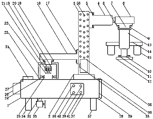
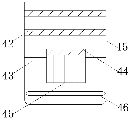
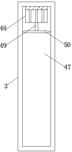
[0028] see Figure 1-5, the present invention provides a technical solution: a continuous stamping robot, including a robot box 1, an electric rotary cylinder 2 is installed on the top right side of the robot box 1, and a robot arm 3 is installed on the top of the electric rotary cylinder 2, A first electro-hydraulic rod 4 is installed on the top of the right side of the robot arm 3, and a first fixing bolt 5 is installed on the left side of the first electro-hydraulic rod 4, and the left side of the first fixing bolt 5 runs through the first electro-hydraulic rod. 4 is connected with a machine arm 3, and the right side of the first electric hydraulic rod 4 is fixedly connected with a first fixed plate 6, and the bottom of the first fixed plate 6 ...


PUM


Abstract

The invention discloses a continuous stamping robot. The continuous stamping robot comprises a robot box body, wherein an electric rotary cylinder is installed on the right side of the top of the robot box body, the top of the electric rotary cylinder is provided with a machine arm, the top of the right side of the machine arm is provided with a first electric hydraulic rod, the left side of the first electric hydraulic rod is provided with a first fixing bolt, the left side of the first fixing bolt penetrates through the first electric hydraulic rod and is connected with the machine arm, andthe right side of the first electric hydraulic rod is fixedly connected with a first fixing plate. According to the continuous stamping robot, a second electric hydraulic rod, a stamping die, a fixingrod, a third electric hydraulic rod and a first motor are arranged, wherein the second electric hydraulic rod, the stamping die and the fixing rod are arranged on the machine arm, the third electrichydraulic rod and the first motor are arranged on the fixing rod, so that the grinding and stamping functions can be simultaneously achieved on the machine arm, the continuous stamping robot not onlycan stamp to-be-stamped parts, but also can grind burrs on the to-be-stamped parts, and therefore the continuous stamping robot is more practical in use, and is suitable for being widely popularized and used.

Description

technical field [0001] The invention relates to the technical field of stamping robots, in particular to a continuous stamping robot. Background technique [0002] At present, stamping is a forming processing method that relies on presses and molds to apply external forces to plates, strips, pipes, and profiles to cause plastic deformation or separation, thereby obtaining workpieces of required shape and size. Existing stamping robots There are many kinds of different design concepts, and strive to meet the needs of different users. Although it can realize the movement of different stamping workpieces, the working range is relatively small, and it can only grab light weight workpieces. It is difficult to be popularized and applied, and the functions of existing stamping robots are relatively single. Stamping parts are often affected by dust particles on the surface during stamping. Not only that, some stamping parts will have burrs on the surface after stamping is completed....

Claims


Application Information

Patent Timeline
Patent Type & Authority Applications(China)
IPC IPC(8): B21D22/02B08B5/02B08B15/04B24B9/00B24B41/06B23P23/00
CPCB08B5/02B08B15/04B21D22/02B23P23/00B24B9/00B24B41/06
Inventor 张晓卫
Owner 张晓卫
Learn More