A pipe beveling machine
A pipe beveling machine and drive motor technology, applied in the field of pipe beveling machines, can solve problems such as laboriousness, incomplete bevel surface, and poor practicability, and achieve convenient and fast replacement, ensure stability, and strong practicability Effect
- Summary
- Abstract
- Description
- Claims
- Application Information
AI Technical Summary
Problems solved by technology
Method used
Image

Examples
Embodiment 1
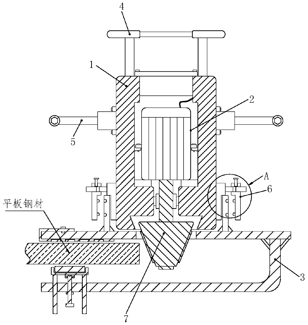
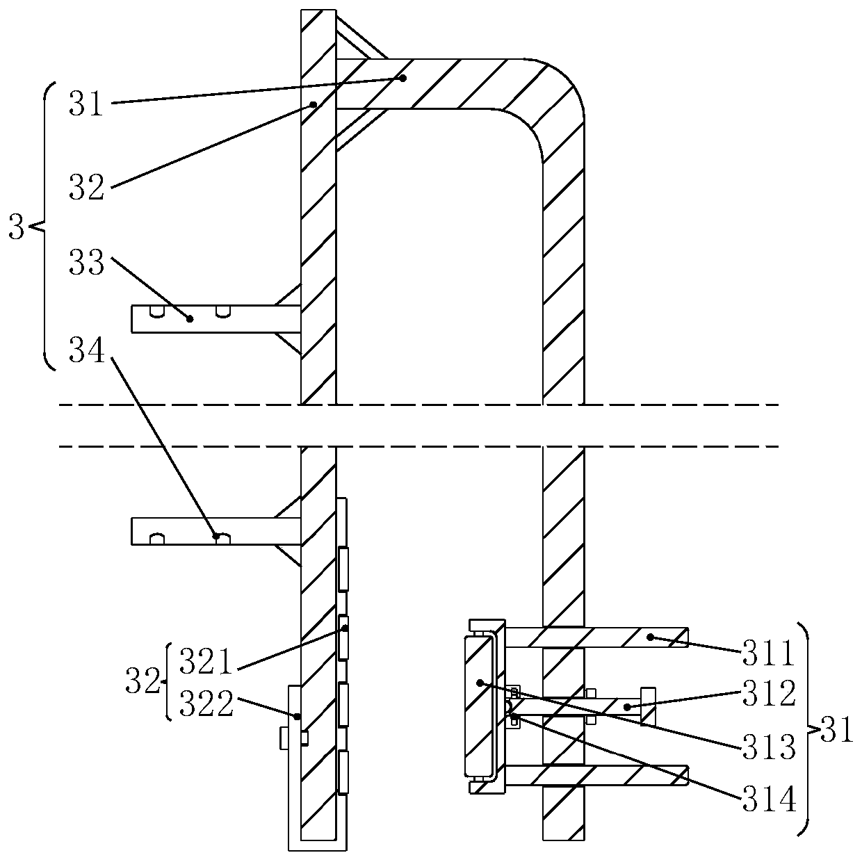
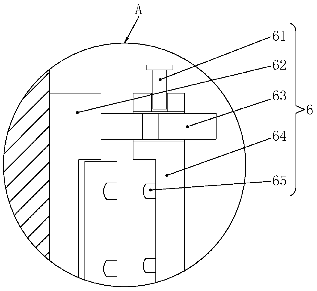
[0029] Referring to 1-3, a pipe beveling machine includes a device housing 1, a drive motor 2, a flat plate fixing assembly 3, a top handle 4, a side handle 5, a connecting assembly 6 and a beveling head 7. The device housing The top of 1 is welded with top handle 4, and the outer walls of both sides of the device shell 1 are equipped with side handles 5 through bolts. The center of the device shell 1 is provided with a motor installation chamber, and the driving motor 2 is installed in the motor installation chamber through the motor fixing frame. In the interior of the chamber, the output shaft of the driving motor 2 is equipped with a bevel cutter head 7 through a coupling, and a connecting assembly 6 is arranged on the outer walls of both sides of the device casing 1 close to the side wing handle 5, and the bottom of the connecting assembly 6 is connected with a flat plate to fix it. component 3;
[0030] The connection assembly 6 includes a latch 61, a support plate 62, a...
Embodiment 2
[0039] like Figure 4-7 As shown, the difference between Embodiment 2 and Embodiment 1 is that the plate fixing assembly 3 is replaced by the pipe fixing assembly 8 .
[0040] In this embodiment, a pipe beveling machine includes a device housing 1, a drive motor 2, a top handle 4, a side handle 5, a connecting assembly 6, a beveling head 7 and a pipe fixing assembly 8, the device housing 1 The top handle 4 is welded on the top, and the outer walls on both sides of the device shell 1 are equipped with side handles 5 through bolts. The center of the device shell 1 is provided with a motor installation chamber, and the driving motor 2 is installed in the motor installation chamber through the motor fixing frame. Inside, the output shaft of the drive motor 2 is equipped with a bevel cutter head 7 through a coupling, and the outer wall on both sides of the device casing 1 is provided with a connecting assembly 6 near the side wing handle 5, and the bottom of the connecting assembly...
PUM
 Abstract
Description
Claims
Application Information
 - R&D Engineer
- R&D Manager
- IP Professional
- Industry Leading Data Capabilities
- Powerful AI technology
- Patent DNA Extraction
Browse by: Latest US Patents, China's latest patents, Technical Efficacy Thesaurus, Application Domain, Technology Topic.
© 2024 PatSnap. All rights reserved.Legal|Privacy policy|Modern Slavery Act Transparency Statement|Sitemap