Double-head supporting winding and unwinding system for printing machine

A printing machine, rewinding and unwinding technology, applied in the printing machine, rotary printing machine, printing and other directions, can solve the problems of aggravating the unwinding and unwinding, inclination or wrinkling, bending and deformation of the middle part of the paper tube, etc. and shaking, avoid bending deformation, the effect of large holding force

Pending Publication Date: 2019-10-15
NEW CENTURY DIGITAL PRINT TECH
View PDF0 Cites 2 Cited by
  • Summary
  • Abstract
  • Description
  • Claims
  • Application Information

AI Technical Summary

Problems solved by technology

This structure is easy to install and disassemble, but it often happens that only the two ends of the paper tube are well supported, while the middle part of the paper tube is in a suspended state, resulting in bending deformation in the middle part of the paper tube, which further aggravates the retraction. Phenomena such as misalignment, tilting or wrinkling during the rolling process

Method used


Image

  • Double-head supporting winding and unwinding system for printing machine
  • Double-head supporting winding and unwinding system for printing machine
  • Double-head supporting winding and unwinding system for printing machine

Examples


Embodiment 1

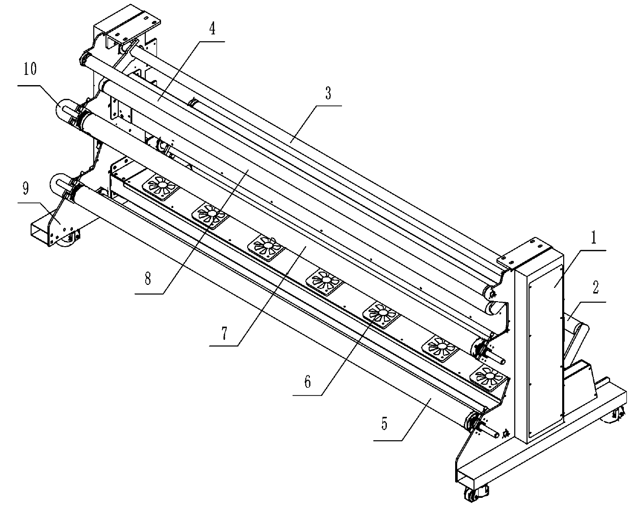
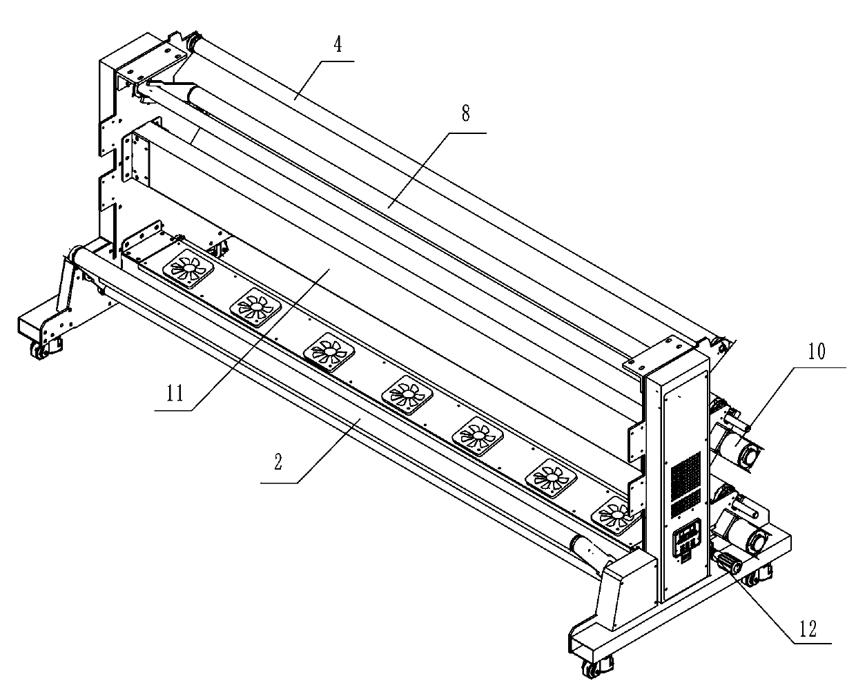
[0026] This embodiment provides a printing machine double-head support retractable system, such as figure 1 , figure 2 , image 3 and Figure 4 As shown, it includes a frame 1 on which an unwinding roller 7 and a winding roller 5 are rotated;

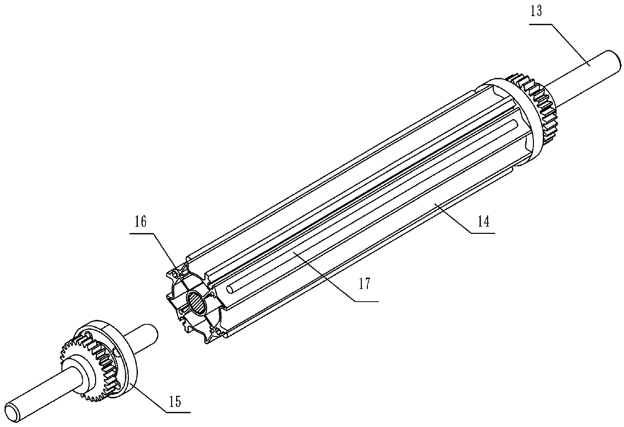
[0027] Both the unwinding roller 7 and the winding roller 5 include a rotating shaft 13 and a supporting profile 14 sleeved on the circumferential surface of the rotating shaft 13 for supporting the paper roll, and the supporting profile 14 is clamped on the surface A plurality of rubber strips 17 are provided, and a rewinding and unwinding motor 10 is drive-connected to each of the rotating shafts 13 .

[0028] Wherein, the rotating shaft 13 and the winding motor 10 are driven by gears.

[0029] In order to facilitate the installation and removal of the winding roller and the unwinding roller from the frame, the length of the rotating shaft 13 is greater than the length of the supporting profile 14, and the protruding parts at bot...

Embodiment 2

[0040] This embodiment provides a double-head support retractable system for a printing machine. The specific structure is roughly the same as that in Embodiment 1. The difference is that in this embodiment, as Figure 5 As shown, the outer surface of the support profile 14 is provided with a plurality of rubber strip positioning concave plates 18 parallel to each other, and a plurality of rubber strips 17 are fixedly arranged in the rubber strip positioning concave plates 18;

[0041] The plurality of rubber strips 17 located in two adjacent rubber strip positioning concave plates 18 are arranged at intervals along the length direction of the rubber strip positioning concave plates 18 .


PUM


Abstract

The invention provides a double-head supporting winding and unwinding system for a printing machine. The double-head supporting winding and unwinding system comprises a machine frame, wherein an unwinding roller, a winding roller, a cloth winding roller, a swing rod supporting rod, an unwinding swing rod, a winding swing rod and a damping roller are rotationally arranged on the machine frame through an integral positioning installing plate, and the cloth winding roller, the swing rod supporting rod, the unwinding swing rod, the winding swing rod and the damping roller are used for supporting aprinting medium to achieve winding and unwinding; and the unwinding roller and the winding roller each comprises a rotating shaft and a supporting profile which sleeves the circumferential surface ofthe rotating shaft, a plurality of rubber strips are clamped on the surface of each supporting profile, and each rotating shaft is in transmission connection with a winding and unwinding motor. According to the system, all the rollers are installed on the integral positioning installing plate, and the winding roller and the unwinding roller are designed into a complete rotating shaft, so that thewhole paper tube can be uniformly supported during winding and unwinding, and the phenomena such as staggering, inclining or wrinkling in the winding and unwinding process are effectively avoided.

Description

technical field [0001] The invention relates to the field of printing machinery, in particular to a double-head support retractable system for a printing machine. Background technique [0002] The existing printing machine equipment usually includes an unwinding roller, a winding roller, a cloth winding roller supporting the transmission of printing media, a swing rod support rod, an unwinding swing rod, a winding swing rod and a damping roller. However, since the existing racks are usually equipped with multiple mounting plates to install the above-mentioned roller systems, the parallelism and installation accuracy between each roller system can only be controlled by the installation workers’ operating level, resulting in poor equipment accuracy. The height and unwinding process are unstable, resulting in misalignment, tilting or wrinkling of the printing medium during printing and rewinding. At the same time, the existing winding roller and unwinding roller are usually co...

Claims


Application Information

Patent Timeline
Patent Type & Authority Applications(China)
IPC IPC(8): B65H75/38B65H75/44B41F17/00B41F17/08
CPCB41F17/00B41F17/08B65H75/38B65H75/4486B65H2701/19B65H2701/53B65H2801/03
Inventor 金利峰
Owner NEW CENTURY DIGITAL PRINT TECH
Why Eureka
Try Eureka