Automobile lifting appliance with linkage and locking mechanisms

A locking mechanism and automobile technology, applied in the directions of transportation and packaging, load hanging components, etc., can solve the problems of large free rolling range, waste of time, left and right sliding, etc., to achieve scientific and reasonable structural design, accurate hoisting positioning, and avoid sliding The effect of displacement

Active Publication Date: 2019-10-15
SINOMACH TIANJIN AUTOMOTIVE EQUIP CO LTD
View PDF3 Cites 4 Cited by
  • Summary
  • Abstract
  • Description
  • Claims
  • Application Information

AI Technical Summary

Problems solved by technology

In the past automobile spreader, the two walking frames are independently rolled and installed at both ends of the hoisting frame. In order to hoist the workpiece, it is necessary to frequently adjust the distance between the two arms, that is, the distance between the two walking frames. When adjusting, the arms on both sides need to be pushed separately Adjustment, adjustment is troublesome and takes up a lot of people; moreover, because the walking frame of the previous automobile spreader is free-rolling and set on the hoisting frame, the free-rolling range is large, and the phenomenon of left-right sliding is easy to occur during the hoisting process, and the stability Poor, temporary fixing is also troublesome and time-consuming

Method used


Image

  • Automobile lifting appliance with linkage and locking mechanisms
  • Automobile lifting appliance with linkage and locking mechanisms
  • Automobile lifting appliance with linkage and locking mechanisms

Examples


Embodiment Construction

[0022] The present invention will be described in further detail below through specific examples. The following examples are only descriptive and not restrictive, and the protection scope of the present invention cannot be limited by this.

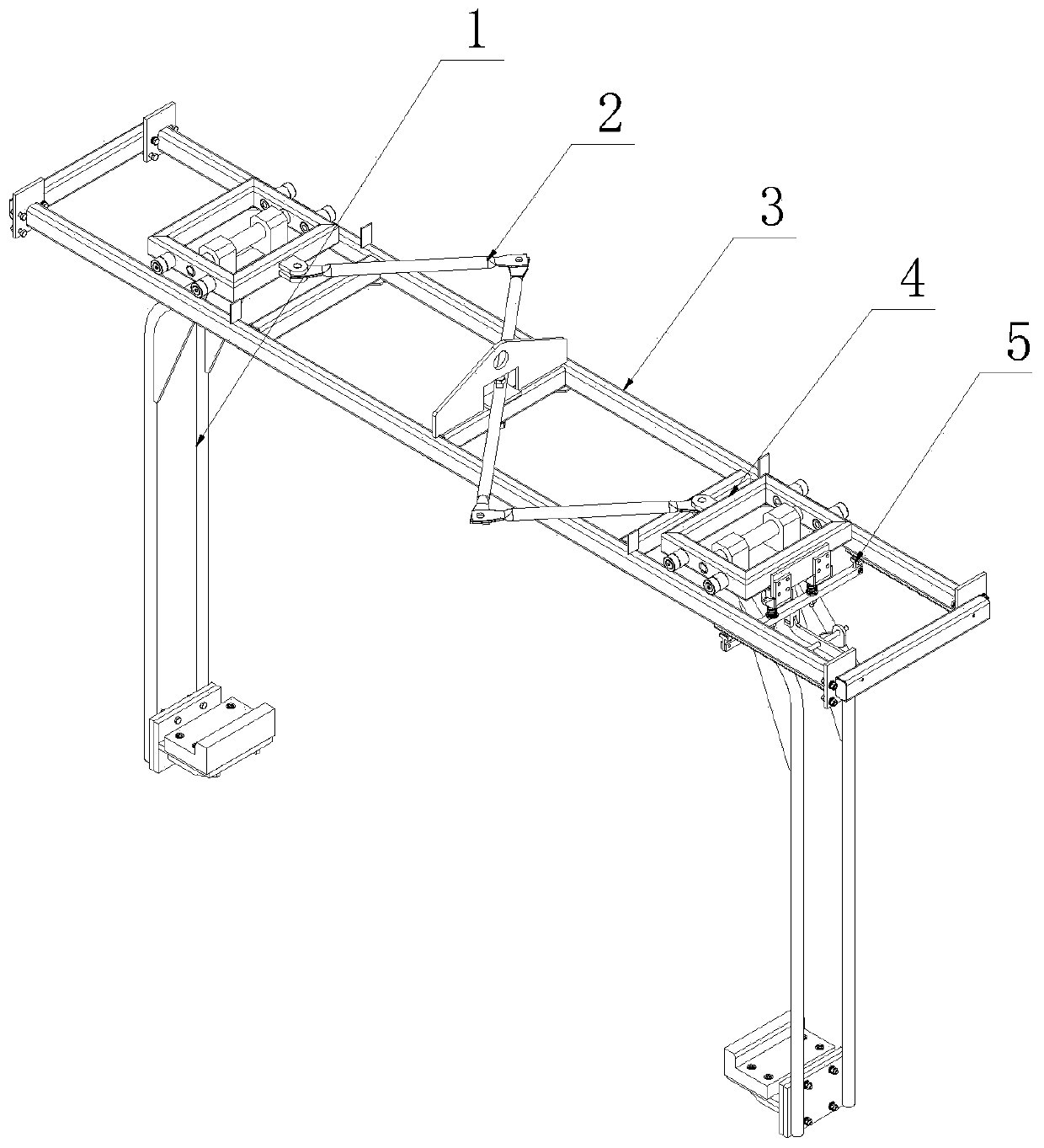
[0023] An automobile sling with a linkage and locking mechanism, comprising a hoisting frame 3, an arm 1, a walking frame 4, and its innovation lies in: it also includes a planar linkage mechanism 2, a locking mechanism 5, and the walking frame is relatively rolling. At both ends of the hoisting frame, the arms are arranged on the walking frame oppositely, the plane linkage mechanism is arranged between the walking frames, one of the locking mechanisms is fixed on the bottom of the hoisting frame, and the lower part of the other is fixed on the arms. The upper part is fixed to the walking frame.

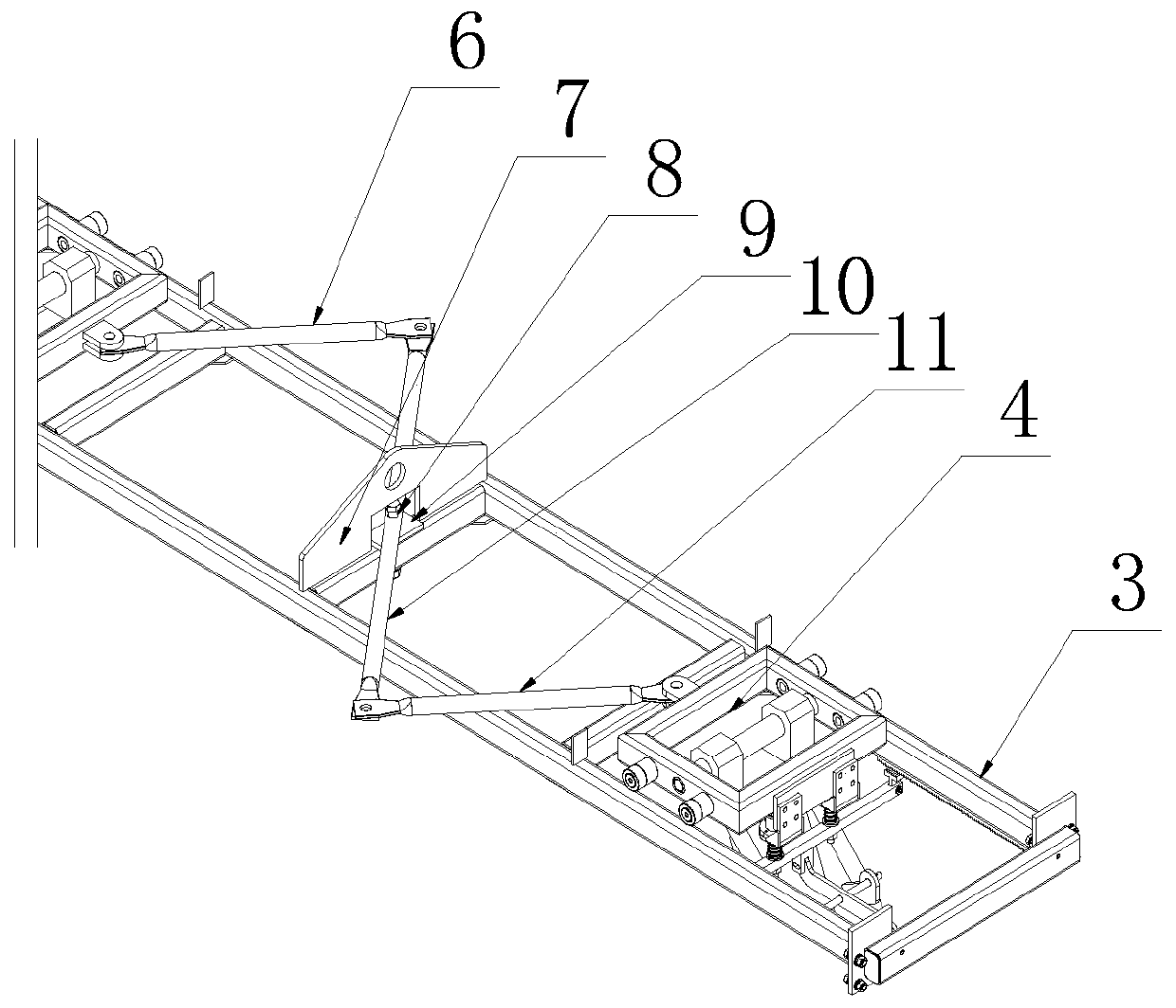
[0024] The plane linkage mechanism is composed of the limit plate 7, the hinge shaft 8, the end linkage rods 6, 11, and the intermediate linkage rod ...


PUM


Abstract

The invention belongs to the technical field of automobile production line equipment, and relates to an automobile lifting appliance with linkage and locking mechanisms. The automobile lifting appliance with the linkage and locking mechanisms comprises a lifting frame, two holding arms, two traveling frames, a plane connecting rod mechanism and the locking mechanisms, wherein the two traveling frames are arranged at two ends of the lifting frame in a relatively rolling mode; the two holding arms are respectively and oppositely arranged on the two traveling frames; the plane connecting rod mechanism is arranged between the two traveling frames; one locking mechanism is fixedly arranged at the bottom of the lifting frame; the upper part of the other locking mechanism is fixedly arranged on the corresponding holding arm, and the lower part of the locking mechanism is fixedly arranged on the corresponding traveling frame; the plane connecting rod mechanism consists of a limiting plate, a hinge shaft, two end linkage rods and a middle linkage rod; the limiting plate is fixedly arranged in the middle of the lifting frame; the hinge shaft is fixedly arranged in the center of the limitingplate; the two end linkage rods are respectively hinged on the two traveling frames; the middle part of the middle linkage rod is rotatably arranged on the hinge shaft; and the two ends of the middlelinkage rod are respectively hinged with the two end linkage rods. The automobile lifting appliance with the linkage and locking mechanisms has the advantages that the structural design is scientificand reasonable, fewer personnel are involved, shorter time and less labor are needed, the sliding displacement of the traveling frames is avoided, the stability is high, and the innovation is higher.

Description

Technical field [0001] The invention belongs to the technical field of automobile production line equipment, and particularly relates to an automobile sling with a linkage and locking mechanism. Background technique [0002] On the automobile production line, the role of the automobile spreader is to grasp the crane head and the body to facilitate the assembly, painting or off-line transportation of them to the designated location. It is mainly composed of a lifting frame, a set of relative arms, and a set of It is composed of a walking frame for installing and adjusting the position of the arm. In the previous automobile slings, the two walking frames are independently rolled and set at both ends of the hoisting frame. In order to hoist the workpiece, the two arms, that is, the distance between the two walking frames, need to be adjusted frequently. When adjusting, the arms on both sides need to be pushed separately. Adjustment and adjustment are troublesome and laborious, and ...

Claims


Application Information

Patent Timeline
Patent Type & Authority Applications(China)
IPC IPC(8): B66C1/30B66C13/04
CPCB66C1/30B66C13/04Y02W30/56
Inventor 沈欢欢肖彦威张建涛王敏姜帅于春乐王斌
Owner SINOMACH TIANJIN AUTOMOTIVE EQUIP CO LTD
Why Eureka
Try Eureka