Wine making purifying device
A linkage and lifting box technology, which is applied in the field of brewing purification devices, can solve the problems of easy clogging of the filter screen, low filtration and purification efficiency, long filtration time, etc., and achieve the effect of improving the filtration effect and the purification and filtration efficiency
- Summary
- Abstract
- Description
- Claims
- Application Information
AI Technical Summary
Problems solved by technology
Method used
Image

Examples
specific Embodiment approach 1
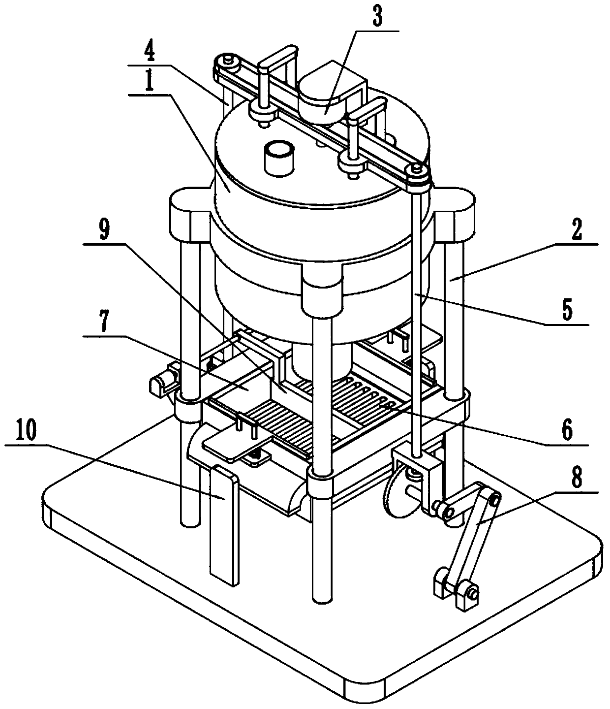
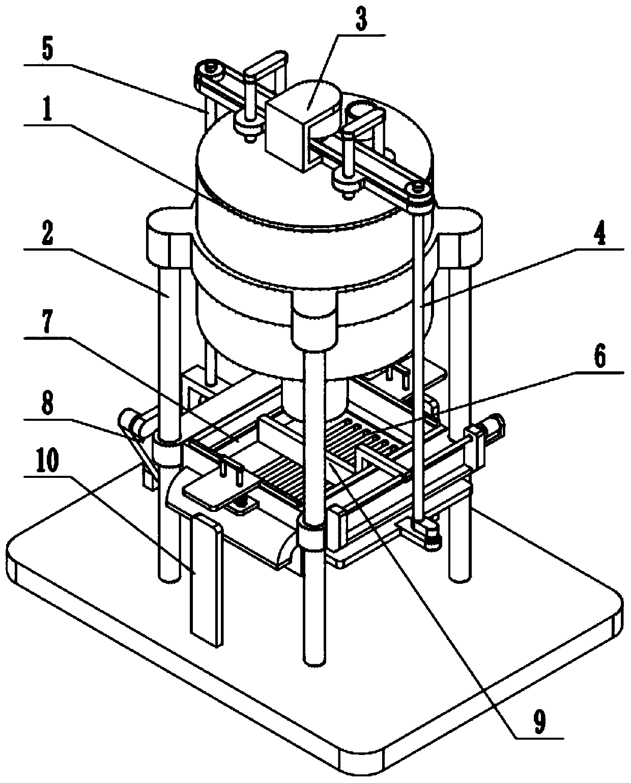
[0032] Such as Figure 1-13 As shown, a brewing purification device includes a transfer drum 1, a stand 2, a lifting plug 3, a left linkage 4, a right linkage 5, a purification filter plate 6, a lifting box 7, a lifter 8 and a base. The transfer drum 1 is fixed on the upper end of the stand 2; the lower end of the stand 2 is fixed on the base; the upper end of the lifting plug 3 is connected to the top of the transfer drum 1, and the lower end of the lifting plug 3 is slidingly fitted on the transfer drum 1 in the wine outlet hole at the bottom; the lifting plug 3 is connected to the left linkage 4 and the right linkage 5; the upper end of the left linkage 4 is connected to the left end of the lifting plug 3 and the lower end of the left linkage Rotationally connected to the left end of the purification filter plate 6, the middle part of the purification filter plate 6 is sealed and slidably fitted in the lifting box 7; the upper end of the right linkage 5 is rotationally conn...
specific Embodiment approach 2
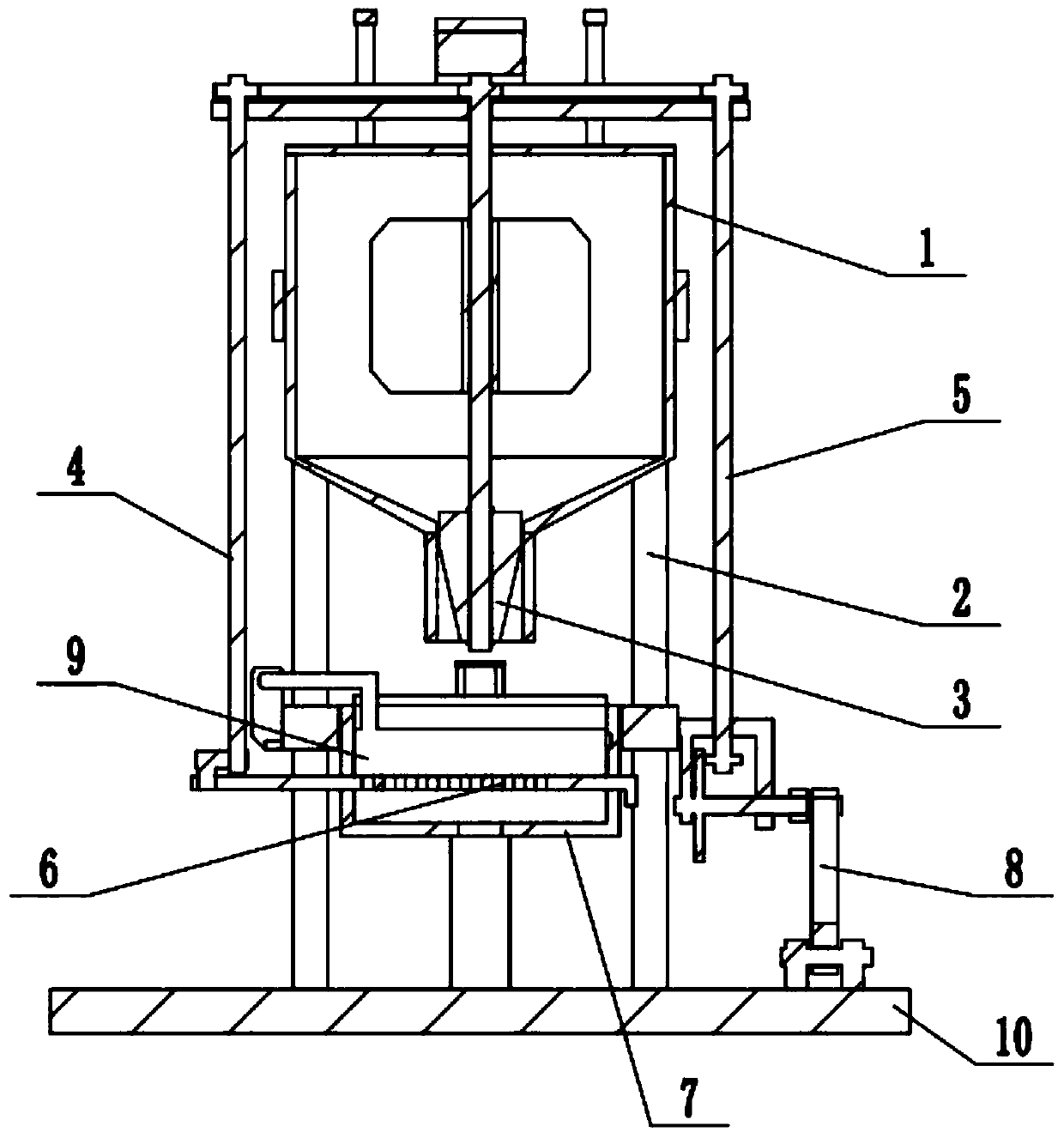
[0034] Such as Figure 1-13As shown, the lifting plug 3 includes a servo motor 301, a driving sprocket 302, a lifting frame 303, a fixed column 304, a top plate 305, a rotating shaft 306, a stirring impeller 307 and an inverted conical plug body 308 without a cone tip; The servomotor 301 is fixed on the lifting frame 303 through the motor base; the output shaft of the servomotor 301 is connected with the rotating shaft 306 through a shaft coupling; the upper end of the rotating shaft 306 is rotated and fitted in the middle of the lifting frame 303; The two ends of the lifting frame 303 are respectively slidably fitted on the two fixed columns 304, and the two fixed columns 304 on the same side are fixedly connected by the top plate 305, and the lower ends of the four fixed columns 304 are all fixed on the top of the transfer drum 1, The upper part of the rotating shaft 306 is sealed and rotated on the top surface of the transfer drum 1, the middle part of the rotating shaft 30...
specific Embodiment approach 3
[0036] Such as Figure 1-13 As shown, the left linkage 4 includes a left sprocket 401, a left linkage shaft 402, a rotating plate 403 and a push-pull shaft 404; The upper and lower ends of 402 are fixedly connected with the left sprocket 401 and one end of the rotating plate 403 respectively; the drive sprocket 302 is connected to the left sprocket 401 through a chain transmission; the other end of the rotating plate 403 is fixedly connected with the push-pull shaft 404; The push-pull shaft 404 is rotatably fitted on the left end of the purification filter plate 6 . The drive sprocket 302 drives the left sprocket 401 to rotate through the chain transmission, and when the left sprocket 401 rotates, it drives the left linkage shaft 402 to rotate, and when the left linkage shaft 402 rotates, it drives one end of the rotating plate 403 to rotate, and The other end drives the push-pull shaft 404 to perform a circular movement, and the push-pull shaft 404 drives the purification fi...
PUM
 Abstract
Description
Claims
Application Information
 - R&D
- Intellectual Property
- Life Sciences
- Materials
- Tech Scout
- Unparalleled Data Quality
- Higher Quality Content
- 60% Fewer Hallucinations
Browse by: Latest US Patents, China's latest patents, Technical Efficacy Thesaurus, Application Domain, Technology Topic, Popular Technical Reports.
© 2025 PatSnap. All rights reserved.Legal|Privacy policy|Modern Slavery Act Transparency Statement|Sitemap|About US| Contact US: help@patsnap.com