
Spraying waste gas mist purification system

A technology of purification system and exhaust gas, which is applied in the fields of climate change adaptation, climate sustainability, chemical instruments and methods, etc., can solve the problems that physical purification methods cannot achieve purification effect, affect workers' health, and affect spraying safety, etc. Achieve the effect of improving the quality of sprayed finished products, improving the utilization rate of paint, and improving the efficiency of filtration and purification

Pending Publication Date: 2021-10-29
广东博硕涂装技术有限公司
View PDF0 Cites 0 Cited by
  • Summary
  • Abstract
  • Description
  • Claims
  • Application Information

AI Technical Summary

Problems solved by technology

In the furniture processing industry, the painting process is the last process of furniture processing. During the spraying operation, there will be highly dispersed paint mist, volatilized solvents, and flying dust around the workpiece during the spraying process. These paint mist, Exhaust mist such as solvents and dust entering the workshop will affect the health of workers, and may catch fire and explode, seriously affecting the safety of spraying. If exhaust mist such as paint mist, solvents, and dust is discharged outside, it will pollute the environment
[0003] Most of the existing spray purification uses wet or dry filtration for purification. For industries with low paint loss, this physical purification method is easy to operate and can meet the process requirements for standard discharge. However, for furniture spray paint For industries with high losses, physical purification methods often fail to achieve good purification effects

Method used


Image

  • Spraying waste gas mist purification system
  • Spraying waste gas mist purification system
  • Spraying waste gas mist purification system

Examples


Embodiment Construction

[0039] The present invention will be further described below in conjunction with the accompanying drawings and embodiments.

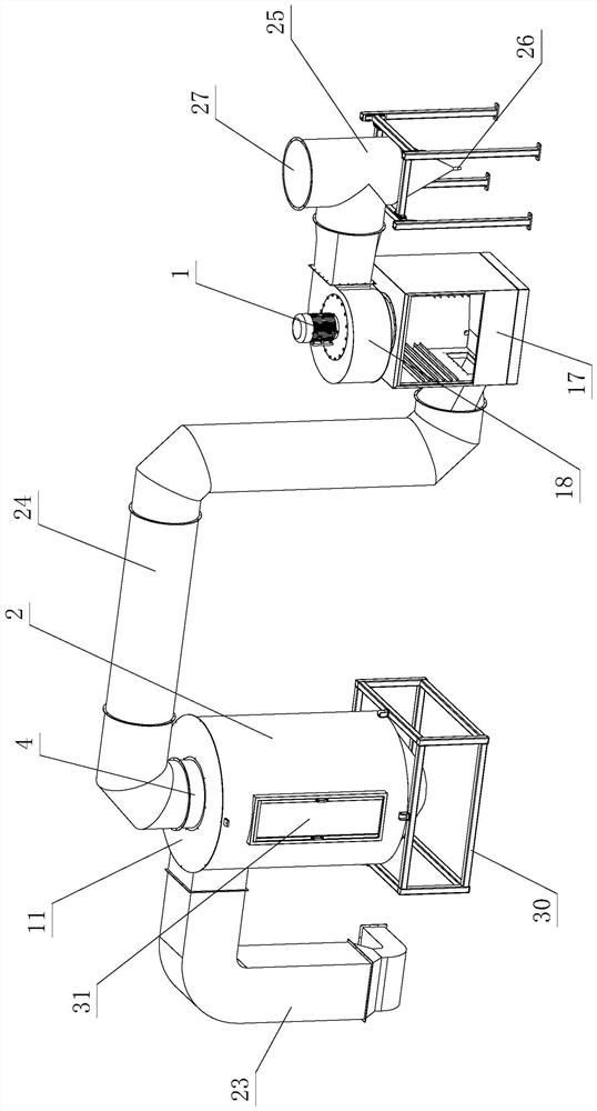
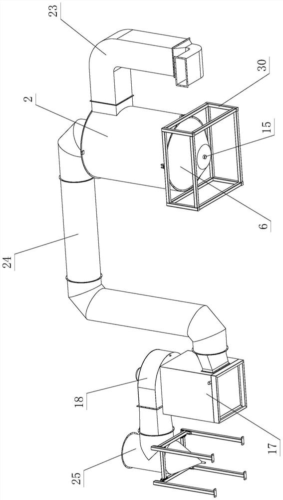
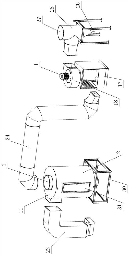
[0040] see Figure 1-Figure 10, the spraying waste gas mist purification system includes a separation device and a fan 1; the separation device at least includes a separation tower 2 and a spiral separation filter element 3; the spiral separation filter element 3 is arranged inside the separation tower 2; the separation tower 2 passes through The spiral separation filter element 3 is separated by a spiral separation area A and a diversion area B which are connected to each other; The exhaust mist passes through the spiral separation area A for spiral separation and filtration, and is discharged outside the separation tower 2 through the diversion area B.

[0041] The spiral separation filter element 3 is composed of a guide tube 4 and a spiral blade 5; the guide tube 4 is in the shape of a hollow cylinder; the spiral blade 5 is spirally arranged on the...


PUM


Abstract

The invention relates to a spraying waste gas mist purification system which comprises a separation device and a fan. The separation device at least comprises a separation tower and a spiral separation filter element; the spiral separation filter element is arranged in the separation tower; the interior of the separation tower is divided into a spiral separation area and a flow guide area, which are communicated with each other, through the spiral separation filter element. The fan is arranged on the outer side of the separation tower and is used for sucking waste gas mist into the separation tower during working, and the waste gas mist in the separation tower is spirally separated and filtered through the spiral separation area and is discharged out of the separation tower through the flow guide area. The waste gas mist is separated and filtered under the spiral centrifugal acting force of the spiral separation area, and the separated and filtered gas is discharged from the flow guide area, so that the waste gas mist such as paint mist, solvent and dust generated when the spraying equipment works is effectively filtered and purified, and the spraying equipment can realize green spraying operation; the harm of the waste gas mist to the health of field personnel and the pollution to the air are reduced.

Description

technical field [0001] The invention relates to the field of purification of paint mist, solvent, dust and other waste gas mist, in particular to a spraying waste gas mist purification system. Background technique [0002] Spraying is the most commonly used coating method nowadays. It has the characteristics of high production efficiency and is suitable for industrial automation production. It is mainly used in furniture, hardware, military industry, ships and other fields. In the furniture processing industry, the painting process is the last process of furniture processing. During the spraying operation, there will be highly dispersed paint mist, volatilized solvents, and flying dust around the workpiece during the spraying process. These paint mist, Exhaust mist such as solvents and dust entering the workshop will affect the health of workers, and may catch fire and explode, seriously affecting the safety of spraying. If exhaust mist such as paint mist, solvents, and dust...

Claims


Application Information

Patent Timeline
Patent Type & Authority Applications(China)
IPC IPC(8): B01D50/00
CPCY02A50/2351
Inventor 胡松刘建雨陈善伟倪洪锐
Owner 广东博硕涂装技术有限公司
Learn More