Parking block mechanism

A blocking mechanism and resistance technology, applied in the field of parking lots, can solve the problems of complicated operation steps, inability to obtain effective release, inability to feedback effective release of resistance, etc.

Inactive Publication Date: 2019-10-15
张宏光
View PDF6 Cites 2 Cited by
  • Summary
  • Abstract
  • Description
  • Claims
  • Application Information

AI Technical Summary

Problems solved by technology

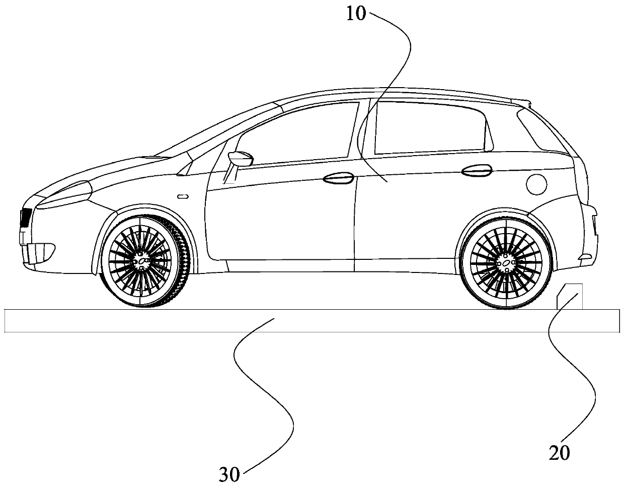
It can be seen that compared with experienced drivers, the novice driver lacks the steps of hanging the N gear and loosening the foot brake, so the feedback resistance produced by the parking blocking lever 20 to the front wheels or the rear wheels cannot be obtained. effective release
[0009] As mentioned above, for experienced drivers, although they can release the generated feedback resistance in the process of parking, the operation steps are unavoidably complicated; and for novice drivers, their operation steps cannot The feedback resistance is effectively released, and the performance of the vehicle will be affected over time

Method used


Image

  • Parking block mechanism
  • Parking block mechanism
  • Parking block mechanism

Examples


Embodiment Construction

[0042] In order to facilitate the understanding of the present invention, the present invention will be described more fully below with reference to the associated drawings. Preferred embodiments of the invention are shown in the accompanying drawings. However, the present invention can be embodied in many different forms and is not limited to the embodiments described herein. On the contrary, the purpose of providing these embodiments is to make the disclosure of the present invention more thorough and comprehensive.

[0043] It should be noted that when an element is referred to as being “fixed” to another element, it can be directly on the other element or there can also be an intervening element. When an element is referred to as being "connected to" another element, it can be directly connected to the other element or intervening elements may also be present. The terms "vertical," "horizontal," "left," "right," and similar expressions are used herein for purposes of ill...


PUM


Abstract

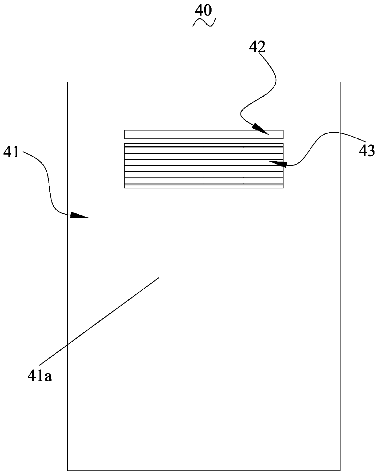
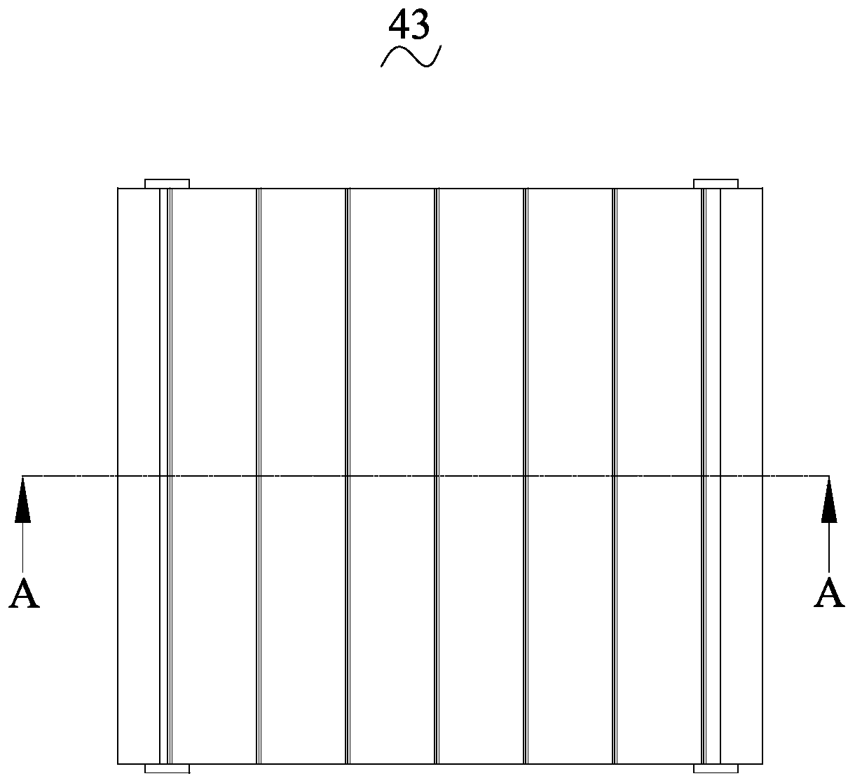
The invention discloses a parking block mechanism. The mechanism comprises a floor, a fixed type block rod, and a feedback resistance releasing device. The fixed type block rod is fixed to the floor,the feedback resistance releasing device is mounted on the floor, and comprises a base, a free rotating shaft, a one-way rotating shaft and a caterpillar band, the free rotating shaft and the one-wayrotating shaft are rotatably arranged on the base, the caterpillar band is in end-to-end connection and is arranged on the free rotating shaft and the one-way rotating shaft in a surrounding manner, first gears are arranged on the two ends of the free rotating shaft, and are engaged with the caterpillar band, second gears are arranged on the two ends of the one-way rotating shaft, and are engagedwith the caterpillar band, a shaft body of the one-way rotating shaft is fixedly sleeved with a ratchet wheel, a one-way blocking piece is rotatably arranged on the base, and one end of the one-way blocking piece is arranged on the face of the ratchet wheel in a pressing manner. According to the parking block mechanism, releasing of feedback resistance is achieved, on one hand, the tedious operation step of an experienced driver is reduced, and on the other hand, the damage of wrong operation of a green-hand driver to the vehicle can be reduced.

Description

technical field [0001] The invention relates to the technical field of parking lots, in particular to a parking blocking mechanism. Background technique [0002] Such as figure 1 As shown, it is a schematic diagram of parking the car 10 into storage. Usually, in the parking lot, people will draw a line in the parking area to obtain a plurality of independent parking spaces, and each independent parking space is used to park a dolly. [0003] In the process of parking, in order to allow the driver to perceive whether the vehicle he is driving is in place, a parking blocking bar 20 is particularly provided on the parking space. When the front or rear wheels of the vehicle touch the parking barrier 20, the parking barrier 20 will generate a feedback resistance to the front or rear wheels of the vehicle, and the driver sitting in the cab will perceive this feedback resistance , so that the driver will know that the current vehicle has parked in place. [0004] As can be seen...

Claims


Application Information

Patent Timeline
Patent Type & Authority Applications(China)
IPC IPC(8): E04H6/42
CPCE04H6/424
Inventor 不公告发明人
Owner 张宏光
Why Eureka
Try Eureka