A kind of array substrate and display panel

A technology for array substrates and display panels, applied in instruments, nonlinear optics, optics, etc., can solve the problems of cutting precision marking static electricity, etc., and achieve the effect of avoiding static electricity problems

Active Publication Date: 2022-03-22
GUANGZHOU GOVISIONOX TECH CO LTD
View PDF8 Cites 0 Cited by
  • Summary
  • Abstract
  • Description
  • Claims
  • Application Information

AI Technical Summary

Problems solved by technology

[0004] The present application provides an array substrate and a display panel, which can improve the problem of static electricity caused by cutting precision marks in the array substrate affected by the wiring area

Method used


Image

  • A kind of array substrate and display panel
  • A kind of array substrate and display panel
  • A kind of array substrate and display panel

Examples


Embodiment Construction

[0027] Certain words are used to refer to specific components in the description and claims, and those skilled in the art should understand that manufacturers may use different terms to refer to the same component. The specification and claims do not use the difference in name as a way to distinguish components, but use the difference in function of components as a basis for distinction. The application will be described in detail below in conjunction with the accompanying drawings and embodiments.

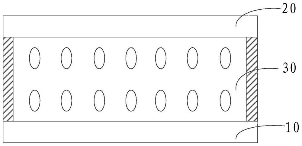
[0028] figure 1 is a schematic structural diagram of a display panel in an embodiment of the present application. Such as figure 1 As shown, the display panel includes an array substrate 10 , a color filter substrate 20 , and a liquid crystal layer 30 sandwiched between the array substrate 10 and the color filter substrate 20 .

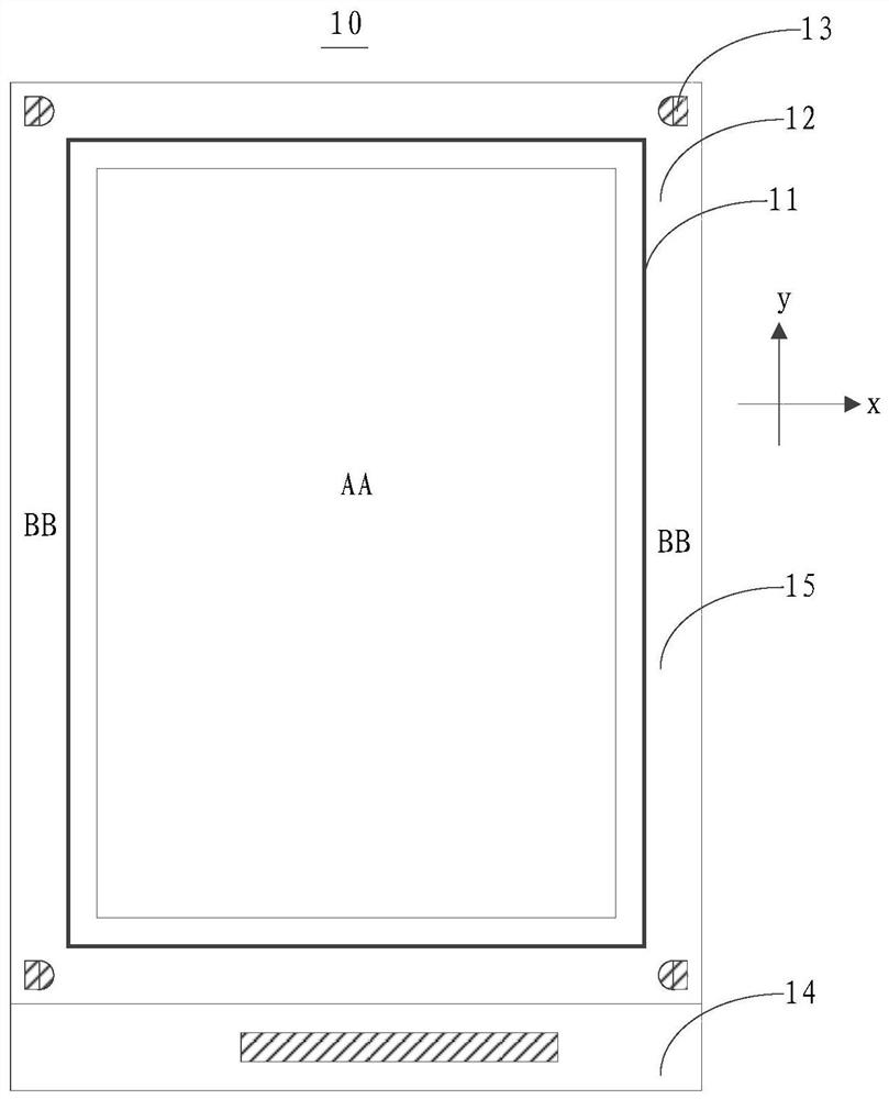
[0029] Please also refer to figure 2 , figure 2 yes figure 1 A schematic diagram of the structure of the array substrate in the display panel sho...


PUM

PropertyMeasurementUnit
diameteraaaaaaaaaa

Abstract

The application discloses an array substrate and a display panel. The array substrate includes a rectangular wiring area and a non-wiring area surrounding the wiring area; in the non-wiring area, at least one cutting accuracy mark is provided at a corner corresponding to the non-wiring area, and the cutting accuracy mark and the wiring area Interval setting; the edge of the cutting accuracy mark close to the routing area is the edge of the curve. The present application can provide a cutting precision mark with a low probability of static electricity generation, so as to meet the requirements of actual production of display panels.

Description

technical field [0001] The present application relates to the field of manufacturing display panels, in particular to an array substrate and a display panel. Background technique [0002] In the field of display panel manufacturing, the manufacturing of display panels usually includes the following process: first, the array substrate and color filter substrate used in the display panel are manufactured, and then the array substrate and the color filter substrate are boxed; The final array substrate and color filter substrate are cut to form a display panel. [0003] Among them, when cutting the array substrate and the color filter substrate after the upper and lower boxes are cut to form the display panel, in order to confirm the cutting accuracy, generally a square cutting accuracy mark is added on the array substrate, and the tip of the square cutting accuracy mark is close to In the wiring area of ​​the array substrate, the probability of static electricity is relatively...

Claims


Application Information

Patent Timeline
Patent Type & Authority Patents(China)
IPC IPC(8): G02F1/1333G02F1/1362
CPCG02F1/1333G02F1/136204
Inventor 李兵李素华梁亚鹏高腾
Owner GUANGZHOU GOVISIONOX TECH CO LTD
Why Eureka
Try Eureka