A high-efficiency deicing device for outdoor cables

An outdoor cable, high-efficiency technology, applied in the direction of cable installation, overhead installation, electrical components, etc., can solve the problems of device instability, poor ice removal effect, etc., to improve work efficiency, facilitate disassembly and installation, and avoid falling fall effect

Active Publication Date: 2020-08-25
ANHUI CABLE
View PDF7 Cites 0 Cited by
  • Summary
  • Abstract
  • Description
  • Claims
  • Application Information

AI Technical Summary

Problems solved by technology

[0003] The purpose of the present invention is to solve the problem of poor ice removal effect and unstable device in the prior art, and propose an outdoor cable efficient deicing device

Method used


Image

  • A high-efficiency deicing device for outdoor cables
  • A high-efficiency deicing device for outdoor cables
  • A high-efficiency deicing device for outdoor cables

Examples


Embodiment 1

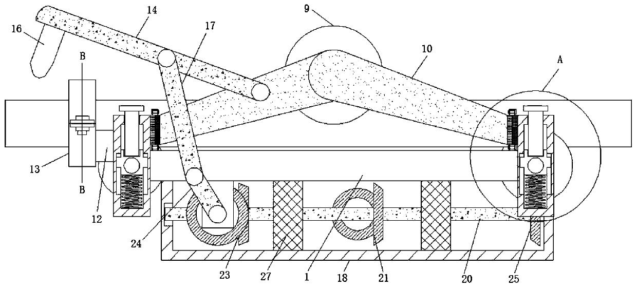
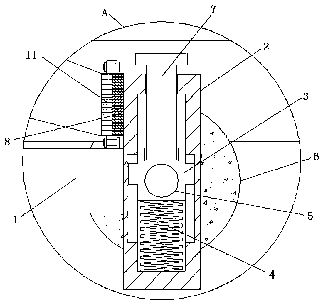
[0029] refer to Figure 1-4 , an outdoor cable high-efficiency deicing device, including a horizontal plate 1, the two side walls of the horizontal plate 1 are fixed with a mounting plate 2 by screws, and the mounting plate 2 is provided with two pieces and symmetrically distributed on the horizontal plate 1 At the front and rear ends, the sides of the two mounting plates 1 and 2 on the same side are all provided with limiting slots, and the limiting slots are slidingly connected with the limiting block 3, and the limiting block 3 and the bottom surface of the limiting slot are fixedly connected with springs 14. An installation shaft 5 is rotatably connected between the two limiting blocks 3 through rolling bearings, and the outer wall of the shaft 5 is fixedly connected with a traveling wheel 6 through screws, and the upper end of the limiting block 3 is rotatably connected with a threaded rod 7 through rolling bearings. , the upper end of the threaded rod 7 passes through th...

Embodiment 2

[0032] Such as Figure 5 and 6 As shown, this embodiment is basically the same as Embodiment 1. Preferably, the ice cube removal device 13 includes a semicircle one 1301 and a semicircle two 1302, and one side of the semicircle one 1301 and the semicircle two 1302 pass through Fixed rotation connection, the outer wall of the other side of semi-circular ring 1301 and semi-circular ring 2 1302 is welded with fixed plate 3 1303, and the two fixed plates 3 1303 are fixed by bolts, semi-circular ring 1 1301 and semi-circular The inner wall of the ring two 1302 is fixed with the installation box 1304 by screws, and the installation box 1304 is provided with two and symmetrically distributed on the inner walls of both sides of the semicircle one 1301 and the semicircle two 1302, the inner walls of the installation box 1304 are all The ice shovel block 1305 is slidingly connected, and the spring two 1306 is fixedly connected between the ice shovel block 1305 and the bottom surface of...

Embodiment 3

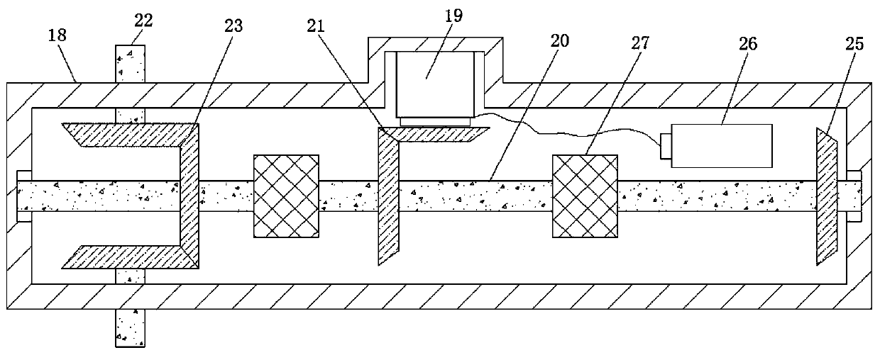
[0035] Such as figure 1 and 2 As shown, this embodiment is basically the same as Embodiment 1. Preferably, both sides of the inner bottom surface of the installation box 18 are fixed with support seats 27 by screws, and the fixed rod 20 is rotatably connected in the support seats 27 through rolling bearings.

[0036] In this embodiment, two fixing seats are provided inside the installation box 18 to ensure a more stable rotation of the fixing rod 20 and ensure the stability of the entire device.


PUM


Abstract

The invention discloses an outdoor cable high-efficiency deicing device, which comprises a horizontal plate, wherein mounting plates 1 are fixed to both side walls of the horizontal plate by screws; two mounting plates 1 are fixed to each of the side walls and are symmetrically distributed on the front end and the rear end of the horizontal plate; the adjacent sides of the two mounting plates on the same side are provided with stopping slots; stopping blocks are slidably connected in the stopping slots; springs 1 are fixedly connected between the stopping blocks and the bottom surfaces of thestopping slots; a mounting shaft is rotatably connected between the two stopping blocks through a rolling bearing; the outer wall of the rod body of the mounting shaft is fixedly connected with a traveling wheel by screws; the upper end of each stopping block is rotatably connected with a threaded rod through a rolling bearing; the upper ends of the threaded rods pass through the mounting plates 1; the sides close to the center of the horizontal plate of the upper ends of the mounting plates 1 are fixedly connected with fixing plate 1 by screws; a suspending wheel is disposed directly above the center position of the horizontal plate; and mounting rods are fixed to the front and rear end walls of the suspending wheel.

Description

technical field [0001] The invention relates to the technical field of auxiliary equipment for cable use, in particular to an outdoor cable high-efficiency deicing device. Background technique [0002] Cables are divided into signal cables and power cables, the former is to transmit signals, such as cable TV optical cables and telephone cables, etc., the latter is to transmit electric energy, communication wires and cables: including local telephones used in urban or local area communication networks Cables, long-distance communication cables used for long-distance communication between cities, local cables and various communication wires, during the use of cables, especially in the cold winter, it is easy to accumulate ice on the surface of the cable due to weather reasons. Ice cubes increase the weight of the cable. In severe cases, the cable or even the iron tower will collapse, resulting in the collapse of power transmission, affecting the use of users, and the existing ...

Claims


Application Information

Patent Timeline
Patent Type & Authority Patents(China)
IPC IPC(8): H02G7/16
CPCH02G7/16
Inventor 夏候东周俊宰学龙韩俊宝徐晓丽朱元忠陈安鹏陶恒莹
Owner ANHUI CABLE
Why Eureka
Try Eureka