Motor control circuit and method

A motor control and circuit technology, which is applied in the direction of AC motor reduction gear, electric motor/converter plug, etc., can solve problems such as high cost and electrical safety risks, and achieve cost-saving effects

Active Publication Date: 2019-10-15
GREE ELECTRIC APPLIANCES INC
View PDF5 Cites 0 Cited by
  • Summary
  • Abstract
  • Description
  • Claims
  • Application Information

AI Technical Summary

Problems solved by technology

Usually, the motor "braking" circuit is a hardware circuit composed of relays or AC contactors. By controlling the relays or AC contactors, the "commutation" processing of the motor's three-phase power line is realized, and the reverse magnetic field is used to generate resistance to the motor. It can stop quickly and achieve the purpose of braking, but this solution uses hardware circuits, which has electrical safety risks and high cost

Method used


Image

  • Motor control circuit and method
  • Motor control circuit and method

Examples


Embodiment Construction

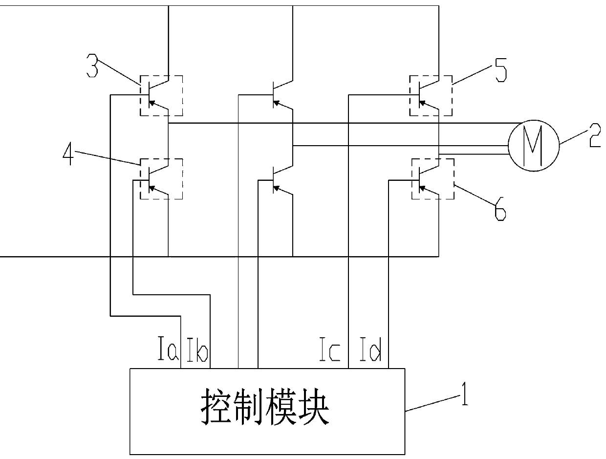
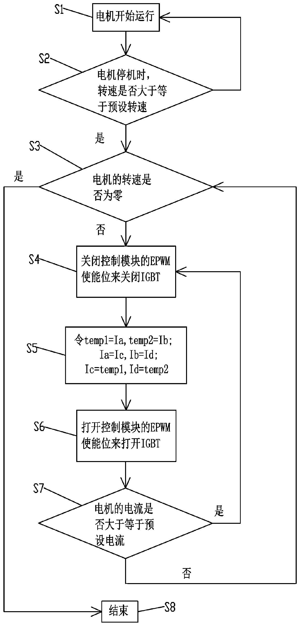
[0027] like figure 1 As shown, the motor control circuit proposed by the present invention is based on a frequency converter. The motor control circuit includes an IGBT connected to the control module 1 and the control module 1, the motor 2 is connected to the IGBT, and the duty of the IGBT is controlled by the control module 1. Compare and change. Swapping the duty cycle controlled by the IGBT through the control module is equivalent to swapping the three-phase power line of the motor, so as to achieve the purpose of "commutation", realize the reversal of the magnetic field, and exert force on the motor rotor by the reverse magnetic field. To achieve the purpose of zero motor speed. The control module is used to reverse the duty cycle of the IGBT control to achieve the purpose of "commutation" of the power supply, and then realize the purpose of stopping the motor at high speed, eliminating the need for relays or AC contactors, saving costs.

[0028] The IGBT has a first up...


PUM


Abstract

The invention discloses a motor control circuit and method. The motor control circuit comprises a control module and an IGBT connected with the control module. A motor is connected with the IGBT; andduty ratios controlled by the IGBT are exchanged by the control module. The duty ratios controlled by the IGBT are exchanged by the control module, which is equivalent to switching of a three-phase power line of the motor, thereby achieving a purpose of "reversing" and realizing reversal of a magnetic field; and the reverse magnetic field exerts an acting force on a rotor of the motor, thereby achieving a purpose that the speed of the motor is zero. The control module is used to exchange the duty ratios controlled by the IGBT to achieve the purpose of power "reversing", thereby realizing a purpose of stopping of the motor at high speed, saving relays or AC contactors and saving cost.

Description

technical field [0001] The present invention relates to the field of motor technology, and more specifically relates to a motor control circuit and method. Background technique [0002] In modern industrial production and daily life, it is often necessary to perform emergency "braking" on the motor to achieve safety or improve production efficiency. Usually, the motor "braking" circuit is a hardware circuit composed of relays or AC contactors. By controlling the relays or AC contactors, the "commutation" processing of the motor's three-phase power line is realized, and the reverse magnetic field is used to generate resistance to the motor. It can stop quickly and achieve the purpose of braking, but this solution uses hardware circuits, which has electrical safety risks and high costs. Contents of the invention [0003] The technical problem to be solved by the present invention is to provide a motor control circuit and method to reduce costs. [0004] The technical solut...

Claims


Application Information

Patent Timeline
Patent Type & Authority Applications(China)
IPC IPC(8): H02P3/20
CPCH02P3/20
Inventor 贺小林王双骥方小斌刘文斌张泽娥
Owner GREE ELECTRIC APPLIANCES INC
Why Eureka
Try Eureka