
Eyeball tracking device

An eye tracking and equipment technology, which is applied in the fields of eye testing equipment, medical science, diagnosis, etc., can solve the problems of large occupied space, fixed usage scenarios, poor scalability, etc., and achieves small occupied space, great convenience, and improved efficiency. Effect

Active Publication Date: 2019-10-18
BEIJING 7INVENSUN TECH +1
View PDF14 Cites 2 Cited by
  • Summary
  • Abstract
  • Description
  • Claims
  • Application Information

AI Technical Summary

Problems solved by technology

However, the supporting equipment of the existing eye tracking equipment is complex, takes up a lot of space, and the use scene is fixed, so it cannot be portable and mobile; and the scalability is poor, and it can only be displayed on the display device connected to itself

Method used


Image

  • Eyeball tracking device
  • Eyeball tracking device
  • Eyeball tracking device

Examples


Embodiment 1

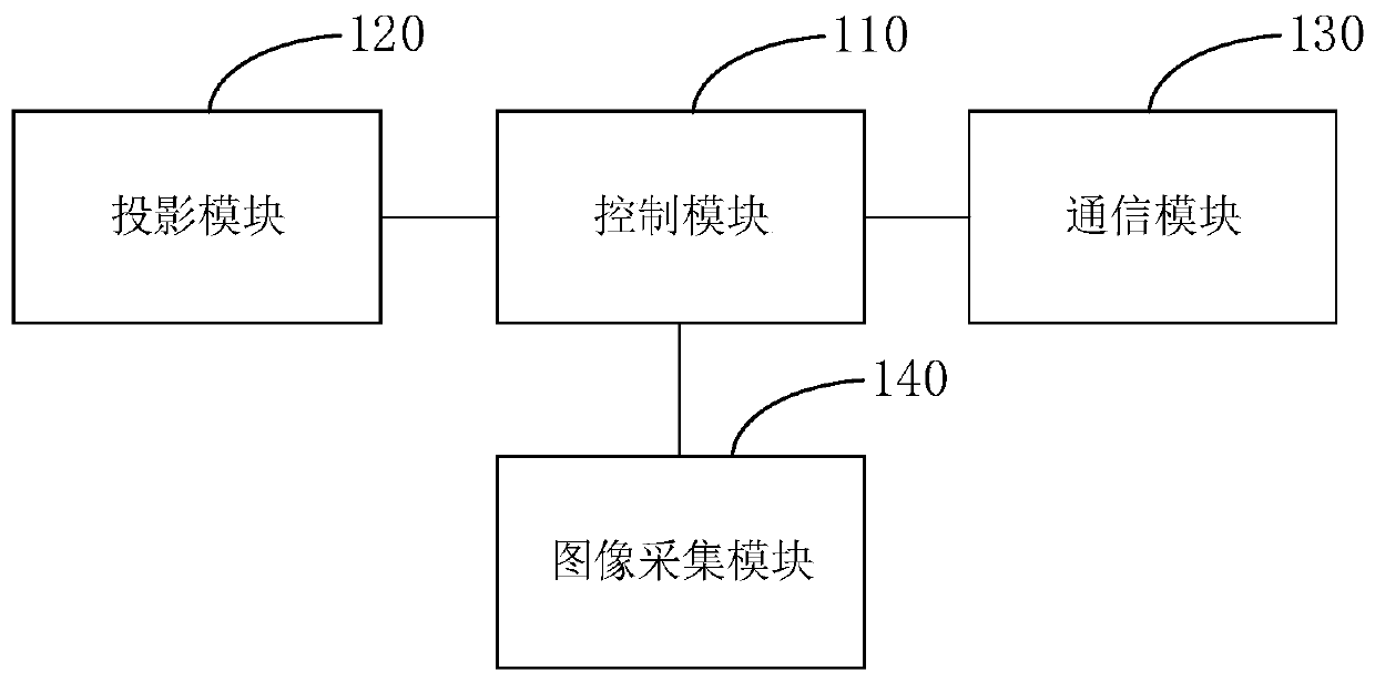
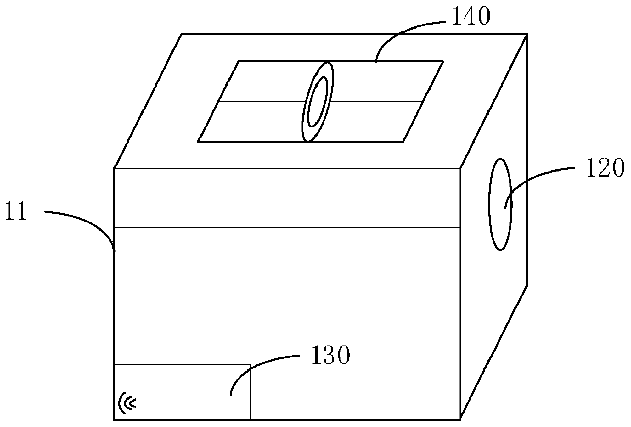
[0037] figure 1 It is a schematic structural diagram of the eye tracking device in Embodiment 1 of the present invention. Such as figure 1 As shown, the eye tracking device may include: a control module 110, a projection module 120, a communication module 130 and an image acquisition module 140, and the control module 110 is connected to the projection module 120, the communication module 130, and the image acquisition module 140 respectively;

[0038] The projection module 120 is used to project calibration light according to the preset target position information to form a calibration mark;

[0039] The image collection module 140 is used to collect user images;

[0040] The control module 110 is used to determine the user's eye parameter information according to the target calibration coefficient calibrated by the target position information combined with the user's image;

[0041] The communication module 130 is configured to send the eye parameter information to the in...

Embodiment 2

[0062] Figure 6 It is a schematic structural diagram of the interactive device in Embodiment 2 of the present invention, and the interactive device is connected to the eye tracking device in the above embodiment.

[0063] Such as Figure 6 As shown, the interaction device may include a display screen and a processor, the processor is configured to determine the gaze information of the user on the display screen according to the eye parameter information sent by the eye tracking device.

[0064] Further, the processor is specifically configured to obtain the first position information of the eye tracking device and the second position information of the display screen; determine the coordinate transformation matrix according to the first position information and the second position information; The internal parameter information is obtained to obtain the processed eyeball conversion information; based on the eyeball conversion information, the user's gaze information on the d...


PUM


Abstract

The invention discloses an eyeball tracking device, which comprises: a control module, a projection module, a communication module and an image acquisition module. The control module is respectively connected to the projection module, the communication module, and the image acquisition module; wherein the projection module is configured to project the calibration light according to the preset target position information to form a calibration identifier; the image acquisition module is configured to collect a user image; the control module is configured to determine the user's eye parameter information according to the target calibration coefficient after the calibration of the target position information and the user image; and the communication module is configured to send the eye parameter information to an interaction device, so that the interaction device determines the gaze information of the user according to the eye parameter information. Compared with the existing eyeball tracking device, the eyeball tracking device provided by the embodiment of the invention has greater convenience, scalability and robustness, and takes up less space, an external display device is not relied, the eyeball tracking device can interact with multiple external interactive devices, and improves the efficiency of the user's eye movement interaction.

Description

technical field [0001] Embodiments of the present invention relate to the technical field of eye control, and in particular, to an eye tracking device. Background technique [0002] An eye-tracking device is a device that can track and measure the position of the eyeball and eye movement information. This device usually tracks the eyeball movement by measuring the position of the gaze point of the eye or the movement of the eyeball relative to the head. [0003] When a user looks at the interface of an eye-tracking device or interacts with an eye-tracking device, the eye-tracking device uses eye-tracking methods to collect detailed technical information and record where the user looks (and does not look) and when. For example, when the user reads text and images, the eye tracking device can record the process of the user's gaze and glance, and completely determine the position of the user's eyes browsing and staying, so as to realize the real-time estimation of the user's fi...

Claims


Application Information

Patent Timeline
Patent Type & Authority Applications(China)
IPC IPC(8): A61B3/113
CPCA61B3/113
Inventor 姚涛杨鑫赵志忠黄通兵
Owner BEIJING 7INVENSUN TECH
Learn More