Eureka AIR delivers breakthrough ideas for toughest innovation challenges, trusted by R&D personnel around the world.

A dumping furnace self-baking electrode volatile dust collector

A technology of self-baking electrodes and volatile matter, which is applied in separation methods, dispersed particle separation, dispersed particle filtration, etc., can solve problems such as joint fractures, achieve the effects of reducing pulling force, prolonging time, and reducing particle content

Active Publication Date: 2021-11-09
重庆市赛特刚玉有限公司
View PDF17 Cites 0 Cited by
  • Summary
  • Abstract
  • Description
  • Claims
  • Application Information

AI Technical Summary

Problems solved by technology

[0005] The invention provides a self-baking electrode volatile dust collector for a dumping furnace to solve the problem in the prior art that the connection between the filter bag and the partition is subjected to pulling force when it vibrates, causing the connection to break

Method used


Image

  • A dumping furnace self-baking electrode volatile dust collector
  • A dumping furnace self-baking electrode volatile dust collector
  • A dumping furnace self-baking electrode volatile dust collector

Examples


Embodiment 1

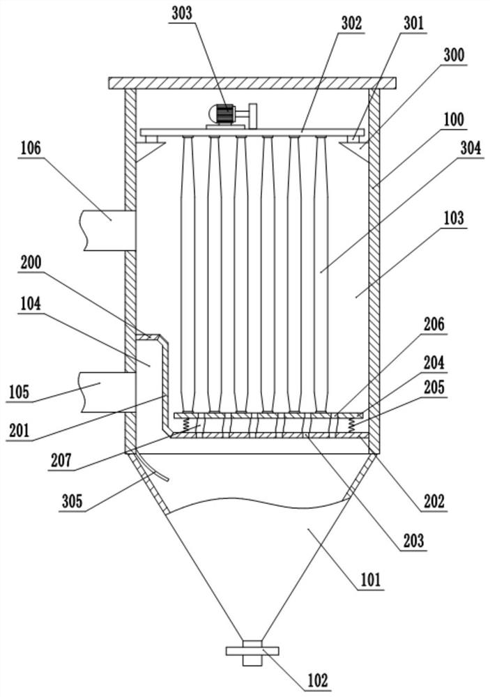
[0035] Embodiment 1 is basically as attached figure 1 Shown:

[0036] A dumping furnace self-baking electrode volatile dust collector, including a box 100 and an ash hopper 101, the ash hopper 101 is fixed below the box 100, the box 100 is supported on the ground by feet or directly fixed on the frame, the box The top and side walls of the body 100 are provided with inspection doors, the bottom of the ash hopper 101 is provided with a sliding door 102, and a partition is fixed horizontally in the box body 100, and the partition board divides the box body 100 into a clean room 103 and a cleaning room 104 , the box body 100 is provided with the air inlet 105 connected to the cleaning chamber 104 and the air outlet 106 connected to the clean room 103, the air inlet 105 and the air outlet 106 are all provided with valves, wherein the partition is Z-shaped, including the top plate 200 , the vertical plate 201 and the horizontal plate 202, the horizontal plate 202 is provided with ...

Embodiment 2

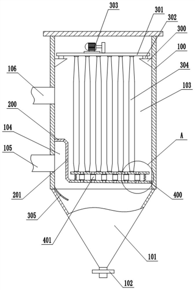
[0045] Embodiment 2 is basically as figure 2 Shown:

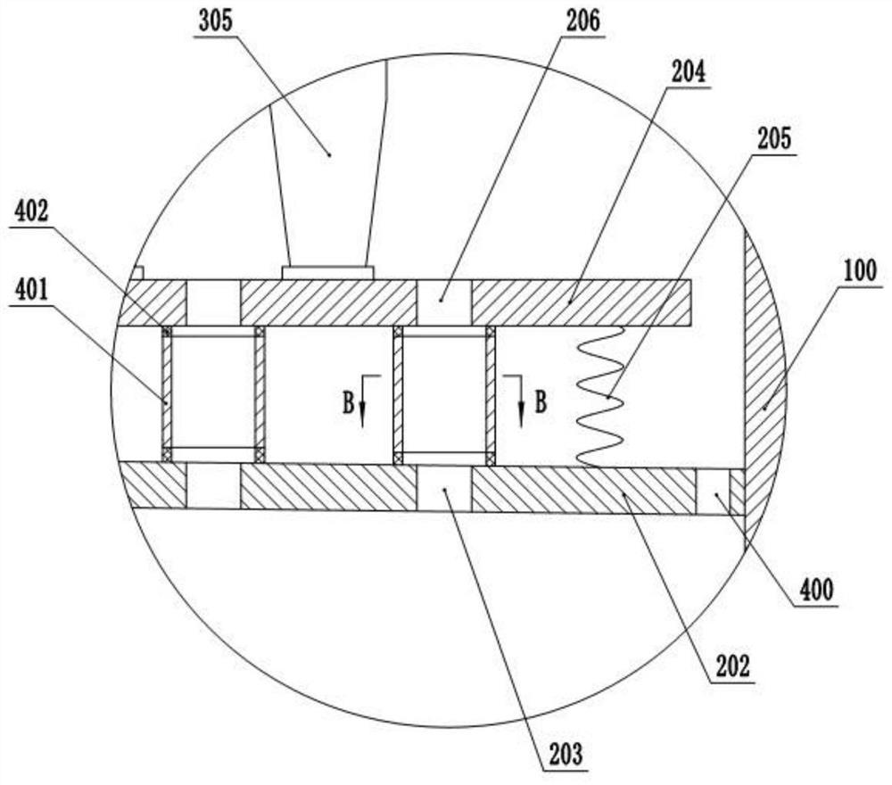
[0046] The difference from Embodiment 1 is that: the end of the horizontal plate 202 away from the air inlet 105 is inclined downward, and the horizontal plate 202 is provided with an ash discharge port 400 on the side away from the air inlet 105, and the through hole I and the through hole II are no longer Misalignment, that is, the adjacent through hole Ⅰ and through hole Ⅱ are set oppositely, and the intermediate pipe is a metal hard pipe 401 made of stainless steel. image 3 As shown, the upper and lower ends of the metal hard tube 401 are fixed with rubber rings 402, the rubber ring 402 at the upper end of the metal hard tube 401 is fixed with the buffer plate 204, and the rubber ring 402 at the lower end of the metal hard tube 401 is fixed with the horizontal plate 202, combined Figure 4 As shown, a horizontal shaft 403 is rotationally and sealedly connected to the side wall of the metal hard tube 401, and the cent...


PUM


Abstract

The invention relates to the technical field of waste gas treatment equipment, and specifically discloses a volatile dust collector for self-baking electrodes of a dumping furnace, which includes a box body and an ash hopper, and a partition is fixed horizontally in the box body, and the partition board divides the box body into a clean room and a cleaning room. There are a plurality of through holes I on the partition, the air inlet connected to the clean room and the air outlet connected to the clean room are arranged on the box body, and a plurality of filter bags located above the partition are vertically arranged in the box body. There is also a vibrating unit for vibrating the filter bag in the body, a buffer plate is arranged above the partition, the bottom of the filter bag is fixed on the buffer plate, the buffer plate and the partition are connected by elastic parts, and the buffer plate A plurality of through holes II are provided, and an intermediate pipe is communicated between the through holes I and II. The use of the dust remover in the present invention can solve the problem in the prior art that the connection between the filter bag and the partition is subjected to a pulling force when it vibrates, causing the connection to break.

Description

technical field [0001] The invention relates to the technical field of waste gas treatment equipment, in particular to a self-baking electrode volatile dust collector for a dumping furnace. Background technique [0002] Self-baking electrodes use anthracite, coke, pitch and tar as raw materials to make electrode paste at a certain temperature, then put the electrode paste into the electrode shell installed on the electric furnace, and then sinter it into shape. This kind of electrode can be used continuously, and it can be sintered and formed while using it. Self-baking electrodes are widely used in brown corundum electric furnaces and calcium carbide furnaces because of their simple process and low cost. [0003] Because in the process of making electrode paste, a certain amount of volatile matter will be produced, which contains particulate matter, dust and other harmful substances. If it is directly discharged, it will not only pose a threat to the health of the staff, b...

Claims


Application Information

Patent Timeline
Patent Type & Authority Patents(China)
IPC IPC(8): B01D46/02B01D46/04B01D50/00
CPCB01D46/023B01D46/04B01D50/20
Inventor 谭华权邓延波匡孝福
Owner 重庆市赛特刚玉有限公司
Why Eureka
Eureka Blog
Learn More