
Protection device for saw-cutting machine with three-axis polar coordinates

A protective device and polar coordinate technology, which is applied to the attachment of sawing machines, metal sawing equipment, maintenance and safety accessories, etc., can solve the problems of working components and sawing mechanism wear, slow manual loading and unloading speed, and potential safety hazards. Achieve the effect of improving precision and cutting efficiency

Inactive Publication Date: 2019-10-18
宁波江北盛亚机械有限公司
View PDF13 Cites 3 Cited by
  • Summary
  • Abstract
  • Description
  • Claims
  • Application Information

AI Technical Summary

Problems solved by technology

[0002] At present, when the existing three-axis sawing machine is used for cutting aluminum profiles, it usually includes a base, two sawing mechanisms and clamping mechanisms on the sawing mechanisms. The debris falling, the protective cover on the sawing machine only has the function of preventing the debris from splashing locally, but cannot clean the waste debris at the transparent window on the protective cover. Long-term use will easily cause waste debris to accumulate at the transparent window. Therefore, due to the viewing effect of the transparent window, the staff cannot accurately understand the cutting conditions inside the sawing mechanism, and the scattered waste can easily cause wear and tear between the working components and the sawing mechanism. , so it is necessary to manually place the aluminum profile to be cut between the two sawing machine mechanisms, and then perform sawing through the clamping mechanism. However, due to manual placement, the length of the aluminum profile to be cut cannot be accurately controlled, which will easily lead to aluminum profile sawing. The cutting length is inaccurate, and the speed of manual loading and unloading is slow and inefficient, and there are certain safety hazards

Method used


Image

  • Protection device for saw-cutting machine with three-axis polar coordinates
  • Protection device for saw-cutting machine with three-axis polar coordinates
  • Protection device for saw-cutting machine with three-axis polar coordinates

Examples


specific Embodiment approach

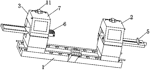
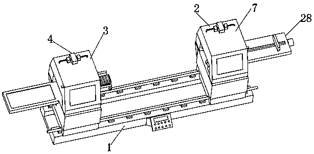
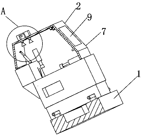
[0033] Specific embodiments: when the first cutting table 2 and the second cutting table 3 are working, the telescopic cylinder 8 operates, so that the two protective covers 7 are attached to the first cutting table 2 and the second cutting table 3 respectively, and Rotate the motor 12 to run, so that the driving gear 13 drives the driven gear 14 to rotate, so that the driven gear 14 drives the screw mandrel 15 to rotate, and because the drive sleeve 17 is rotated and socketed on the outside of the screw mandrel 15, the drive sleeve 17 is received by the drive rod 18 at the same time. The limit function of the sliding sleeve 23 at the other end makes the driving rod 18 move relative to the transparent window 9, thereby driving the brush 20 to clean the transparent window 9. At the same time, the two exhaust fans 25 run to make the aluminum The waste chips generated during profile cutting enter into the dust collection box 24 through the dust suction head 27, so as to realize th...


PUM


Abstract

The invention discloses a protection device for a saw-cutting machine with three-axis polar coordinates. The protection device for the saw-cutting machine with the three-axis polar coordinates comprises a base, a first cutting table and a second cutting table, wherein the first cutting table and the second cutting table are symmetrically distributed on the base. According to the protection devicefor the saw-cutting machine with the three-axis polar coordinates, firstly, waste chips at a transparent window in a protection cover are cleaned in time through waste cleaning devices arranged on thefirst cutting table and the second cutting table; auxiliary charge can be carried out according to the needed cutting length through a charge device arranged on the first cutting table; auxiliary discharge is carried out on a cut aluminum profile between the first cutting table and the second cutting table, so that potential safety hazards existing due to the manual direct contact with the firstcutting table and the second cutting table are avoided, and meanwhile, the cutting accuracy for the aluminum profile is increased; and moreover, a protection role during cutting for the aluminum profile is played, and the cutting efficiency of the saw-cutting machine is increased.

Description

technical field [0001] The invention relates to the technical field of sawing machines, in particular to a protective device for a three-axis polar coordinate sawing machine. Background technique [0002] At present, when the existing three-axis sawing machine is used for cutting aluminum profiles, it usually includes a base, two sawing mechanisms and clamping mechanisms on the sawing mechanisms. The debris falling, the protective cover on the sawing machine only has the function of preventing the debris from splashing locally, but cannot clean the waste debris at the transparent window on the protective cover. Long-term use will easily cause waste debris to accumulate at the transparent window. Therefore, due to the viewing effect of the transparent window, the staff cannot accurately understand the cutting conditions inside the sawing mechanism, and the scattered waste can easily cause wear and tear between the working components and the sawing mechanism. , so it is neces...

Claims


Application Information

Patent Timeline
Patent Type & Authority Applications(China)
IPC IPC(8): B23D59/00B23Q11/00B23Q7/00B23Q17/22B23Q11/08
CPCB23D59/00B23Q11/00B23Q7/00B23Q17/22B23Q11/08B23Q11/0042B23Q11/0046
Inventor 林国平
Owner 宁波江北盛亚机械有限公司
Learn More