Hair shaving knife head

A razor and cutter head technology, applied in the field of cutter head assembly and shaving cutter head, can solve the problems affecting the end face fit of the movable cutter head and the fixed cutter, affecting the hair shaving efficiency, affecting the shaving effect, etc. Achieve the effect of improving surface utilization, improving shaving effect, and improving shaving efficiency

Pending Publication Date: 2019-10-18
浙江海顺电工有限公司
View PDF1 Cites 11 Cited by
  • Summary
  • Abstract
  • Description
  • Claims
  • Application Information

AI Technical Summary

Problems solved by technology

[0002] A patent assigned by the applicant: reciprocating razor middle knife, announcement number: CN100575008C, announcement date: 2009-12-30, which specifically discloses M-type fixed knife and M-like moving knife , and a spring is provided on the moving knife seat to ensure that the end faces of the moving knife and the fixed knife fit together. Although this type of structure can achieve hair shaving, it also has obvious defects during production and use. For example, the outer The cutting horizontal groove of the knife net (that is, the fixed knife) is semi-closed, and long hair or curly hair cannot enter the cutting horizontal groove, which affects the hair shaving efficiency; secondly, the moving knife head is only fixed in the base by a spring , when the driving mechanism drives the moving head to swing back and forth, it is prone to offset or misalignment, which will affect the fit between the end face of the moving head and the fixed knife, and affect the shaving effect

Method used


Image

  • Hair shaving knife head
  • Hair shaving knife head
  • Hair shaving knife head

Examples


Embodiment Construction

[0023] Embodiments of the present invention will be further described below in conjunction with accompanying drawings:

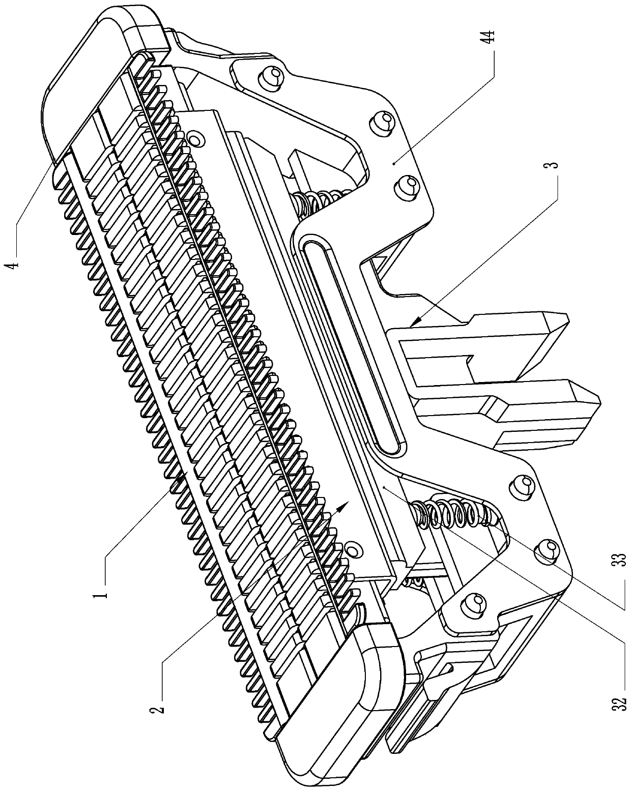
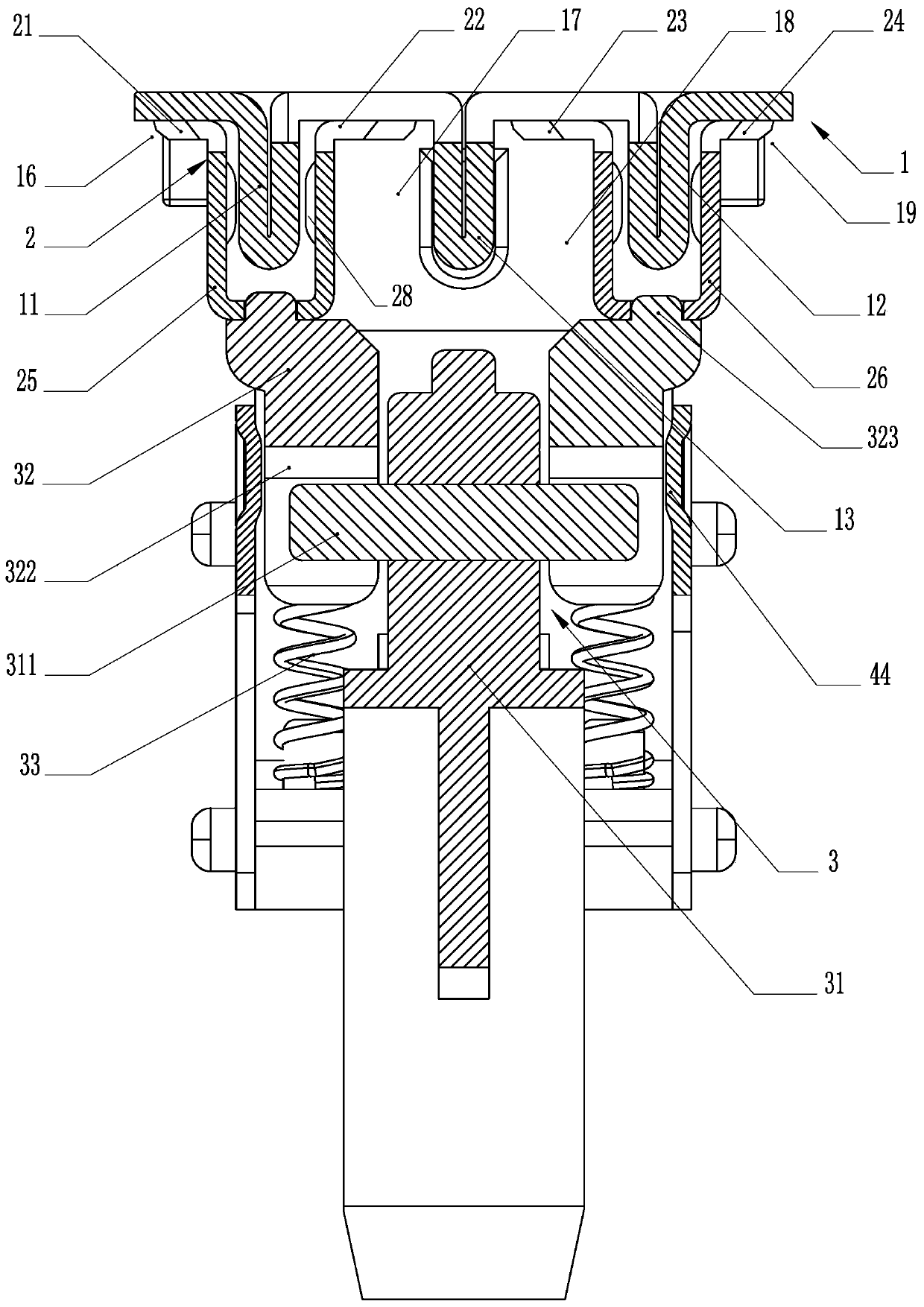
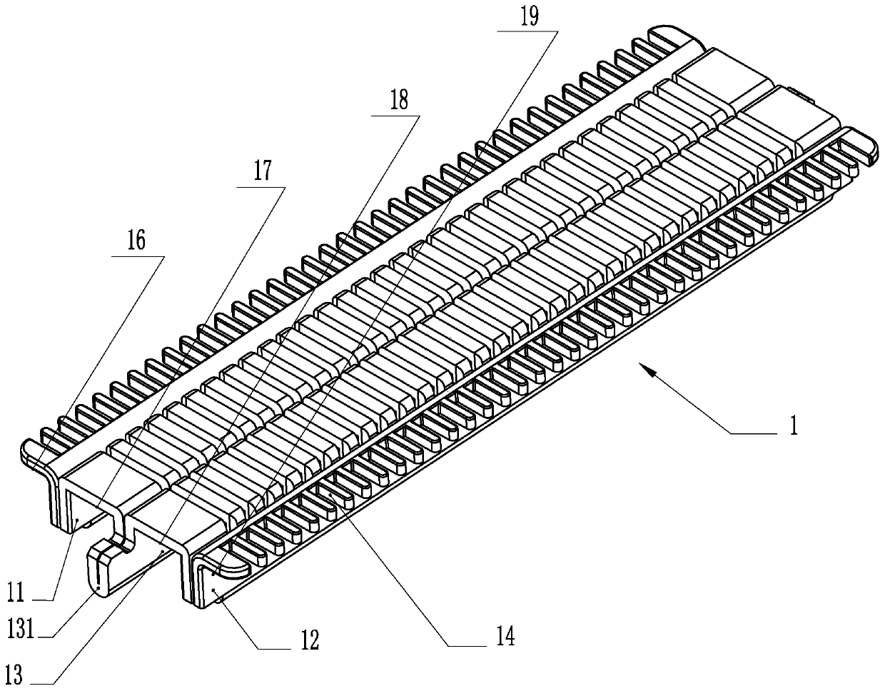
[0024] like Figure 1-8 As shown, the present invention is a shaving head, which includes an outer knife net 1 and an inner knife head 2, the inner knife head 2 is installed on the inner knife seat 3, and the bottom of the outer knife net 1 is provided with a first guide rail 11. The second guide rail 12 and the fixed guide rail 13 make the bottom of the outer knife net 1 form the first sipe 16, the second sipe 17, the third sipe 18 and the fourth sipe 19. In the first sipe 16 , the second sipe 17, the third sipe 18 and the fourth sipe 19 are respectively provided with a beard inlet groove 14, and one end of the first sipe 16 and the fourth sipe 19 is an opening. The fixed guide rail 13 is placed between the first guide rail 11 and the second guide rail 12, and the two ends of the fixed guide rail 13 are respectively connected with the base 4 so that the ou...


PUM


Abstract

The invention relates to a hair shaving knife head. The hair shaving knife head is characterized in that a first guide rail, a second guide rail and a fixed guide rail are arranged at the bottom of anouter knife net, so that a first knife groove, a second knife groove, a third knife groove and a fourth knife groove are formed in the bottom of the outer knife net, one end of a hair inlet groove ineach of the first knife groove and the fourth knife groove is open and communicates with the outside, inner knife heads are correspondingly placed in the first knife groove, the second knife groove,the third knife groove and the fourth knife groove and are correspondingly attached to the bottom end faces of the first knife groove, the second knife groove, the third knife groove and the fourth knife groove. The hair shaving knife head has the beneficial effects that the first guide rail, the second guide rail and the fixed guide rail are arranged at the bottom of the outer knife net, so thatthe four independent knife grooves are formed in the bottom of the outer knife net, by adopting the structure of the four knife grooves, the length of the knife head in each knife groove can be shortened, the flatness forming requirement of the single knife head is correspondingly lowered, the machining difficulty of the knife head is reduced, the production benefit of the knife head is improved,and the production cost of the knife head is reduced.

Description

technical field [0001] The present invention relates to a cutter head assembly, more specifically to a razor head, which is mainly used in the field of razors. Background technique [0002] A patent assigned by the applicant: reciprocating razor middle knife, announcement number: CN100575008C, announcement date: 2009-12-30, which specifically discloses M-type fixed knife and M-like moving knife , and a spring is provided on the moving knife seat to ensure that the end faces of the moving knife and the fixed knife fit together. Although this type of structure can achieve hair shaving, it also has obvious defects during production and use. For example, the outer The cutting horizontal groove of the knife net (that is, the fixed knife) is semi-closed, and long hair or curly hair cannot enter the cutting horizontal groove, which affects the hair shaving efficiency; secondly, the moving knife head is only fixed in the base by a spring , when the driving mechanism drives the mova...

Claims


Application Information

Patent Timeline
Patent Type & Authority Applications(China)
IPC IPC(8): B26B19/12B26B19/38
CPCB26B19/12B26B19/3813
Inventor 钟海勇
Owner 浙江海顺电工有限公司
Why Eureka
Try Eureka