Lateral bunker bay structure of large-scale thermal power plant

A technology for thermal power plants and side coal bunkers, applied in industrial buildings, etc., can solve the problems of reducing beam section and self-weight, increasing structural span, and inconvenient equipment maintenance, achieving the effect of reducing span, reducing transverse span, and saving materials

Active Publication Date: 2014-09-03
CEEC JIANGSU ELECTRIC POWER DESIGN INST
View PDF3 Cites 0 Cited by
  • Summary
  • Abstract
  • Description
  • Claims
  • Application Information

AI Technical Summary

Problems solved by technology

[0003] From the perspective of the structural form of the side coal bunkers, after the Wenchuan Earthquake, the national earthquake resistance regulations started from improving the "redundancy", requiring high-rise buildings not to use a single-span frame structure with two columns, so the conventional side coal bunkers generally A frame structure with three or four columns is adopted, but the addition of intermediate columns requires the coal mills corresponding to the two boilers to be equipped with corresponding maintenance channels in terms of process layout, which not only increases the span of the structure, but also brings new benefits to equipment maintenance. inconvenient
[0004] In order to avoid single frame, some projects adopt the structure of anti-seismic wall or short-leg anti-seismic wall in the structure between side coal bunkers. ), therefore, in order to reflect the seismic design concept of “strong columns and weak beams” and reduce the cross-section and self-weight of the beams, columns are generally installed in the middle of the side coal bunkers, so that in the actual use process, maintenance is inconvenient and the overall structure large span

Method used


Image

  • Lateral bunker bay structure of large-scale thermal power plant
  • Lateral bunker bay structure of large-scale thermal power plant
  • Lateral bunker bay structure of large-scale thermal power plant

Examples


Embodiment Construction

[0024] In order to further explain the technical means and functions adopted by the present invention to achieve the intended purpose of the invention, the specific implementation modes of the present invention will be further described in detail below in conjunction with the accompanying drawings and preferred embodiments.

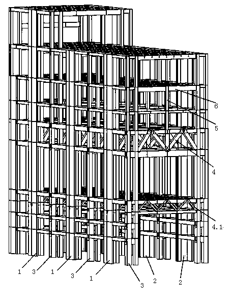
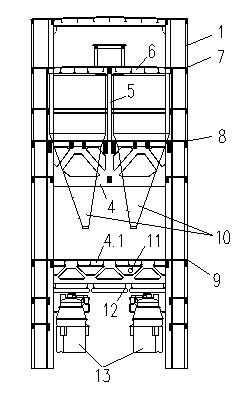
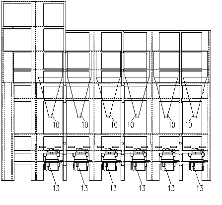
[0025] As shown in the figure, a large thermal power plant side coal bunker structure includes a frame beam 6, and longitudinal anti-seismic walls 1, transverse anti-seismic walls 2 and lattice frame columns 3 scattered around the frame beam 6, respectively. Frame beam 6, longitudinal seismic wall 1, transverse seismic wall 2, and lattice frame column 3 are all rigidly connected to form a complete lateral force-resistant structural system. , the lower chord section is far smaller than the wall and column, so the design idea of ​​"strong column and weak beam" in which the beam joints fail before the column can be fully realized through the adjustment of the...


PUM


Abstract

The invention discloses a lateral bunker bay structure of a large-scale thermal power plant. The lateral bunker bay structure comprises a belt layer, a coal bucket bearing layer and an operation layer, wherein the lateral bunker bay structure of the large-scale thermal power plant is dispersedly provided with transverse earthquake resistant walls and longitudinal earthquake resistant walls on the periphery, a framework column of the lateral bunker bay structure of the large-scale thermal power plant adopts a latticed column, the operation layer and the coal bucket bearing layer are respectively arranged on a reinforced concrete truss girder, and the belt layer and the framework column are supported through a converting column. The lateral bunker bay structure of the large-scale thermal power plant belongs to a reinforced concrete main plant structure system suitable for generator sets in high-intensity earthquake regions, and compared with the traditional structure system, the lateral bunker bay structure has the advantages that the self weight is light, materials are saved, and the component stress is more reasonable. The safety degree and the earthquake resistant performance of the structure are greatly improved, in the process arrangement aspect, great convenience is brought to the process arrangement and the operation through the ingenious structure layout, and the maintenance cost in the later period is reduced.

Description

technical field [0001] The invention belongs to the technical field of plant design, and relates to a novel main plant structure system of a large-scale thermal power plant. Background technique [0002] The power plant is an important part of the national energy construction, and the main plant is the core building of the power plant, and its layout is directly related to the safe and economical operation, maintenance and project cost of the power plant. Compared with the traditional front coal bunker scheme, the side coal bunker layout of the main plant can effectively reduce the material consumption of the four major pipelines and save cost and save land. [0003] From the perspective of the structural form of the side coal bunkers, after the Wenchuan Earthquake, the national earthquake resistance regulations started from improving the "redundancy", requiring high-rise buildings not to use a single-span frame structure with two columns, so the conventional side coal bunk...

Claims


Application Information

Patent Timeline
Patent Type & Authority Patents(China)
IPC IPC(8): E04H5/02
Inventor 徐昆郝俊涛王铁菊刘欣良葛小丰许宁朱庆东杜小庆葛新锋卢红前沈涛
Owner CEEC JIANGSU ELECTRIC POWER DESIGN INST
Why Eureka
Try Eureka