Eureka AIR delivers breakthrough ideas for toughest innovation challenges, trusted by R&D personnel around the world.

Pneumatic ejection mold

A pneumatic and ejection technology, applied to presses, manufacturing tools, etc., can solve problems such as difficulty in finding equipment failures, high costs, and inaccurate judgments, and achieve the effects of simple structure, good use effect, and cost reduction

Active Publication Date: 2019-10-18
杭州富阳通讯塑料厂
View PDF7 Cites 0 Cited by
  • Summary
  • Abstract
  • Description
  • Claims
  • Application Information

AI Technical Summary

Problems solved by technology

But this patent has the following problems: First, there is mechanical noise in the production process, and it is not easy for the staff on duty to distinguish whether the sound of the steel ball colliding with the metal contact piece is regular or not, so it is difficult to To distinguish whether the equipment is working normally; second, the ejection of the formed workpiece is completed by an air extraction device, the arrangement of the air extraction device leads to a redundant structure, high cost, and complicated maintenance; third, through the collision between the steel ball and the metal contact piece There is still such a disadvantage in judging whether the equipment is normal by the interval of the sound emitted. Due to human hearing fatigue, the judgment of the interval is easy to be inaccurate, and it is likely to make it difficult to find equipment failures.

Method used


Image

  • Pneumatic ejection mold
  • Pneumatic ejection mold
  • Pneumatic ejection mold

Examples


Embodiment Construction

[0041] The present invention will be described below with reference to the accompanying drawings; however, it should be understood that these descriptions are illustrative only and are not intended to limit the scope of the present disclosure. Also, in the following description, descriptions of well-known structures and techniques are omitted to avoid unnecessarily obscuring the concepts of the present disclosure. All terms (including technical and scientific terms) used herein have the meaning commonly understood by one of ordinary skill in the art, unless otherwise defined. It should be noted that the terms used herein should be interpreted to have a meaning consistent with the context of this specification, and not be interpreted in an idealized or overly rigid manner.

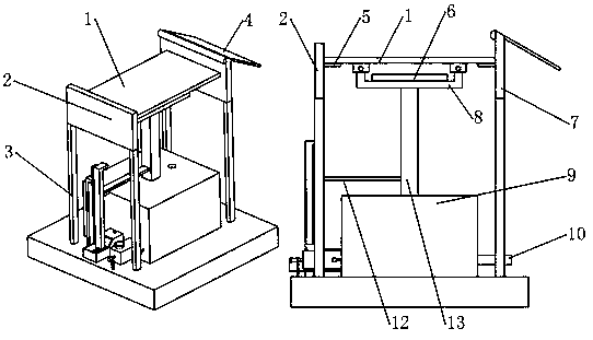
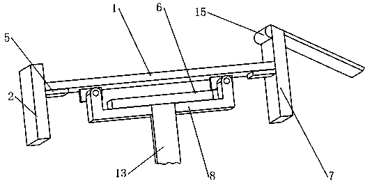
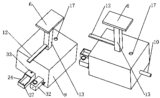
[0042] A pneumatic ejection mold, such as figure 1 , 4 , 6, and 11, it includes push plate 1, A support plate 2, slide plate 4, support plate 5, push platform 6, B support plate 7, U-shaped plate A8, cyli...


PUM


Abstract

The invention belongs to the technical field of molds and particularly relates to a pneumatic ejection mold. The pneumatic ejection mold comprises a push plate, a supporting plate A, a sliding plate,a push table, a piston A, a base, a shell A, a loudspeaker, a spring B, a rotary rod, a clamping block B, a shell C and the like. The pneumatic ejection mold is provided with the pneumatic alarm loudspeaker, a conical plug, a telescopic rod and the spring B. When equipment has an exception, the conical plug is pushed open by air pressure, the pneumatic alarm loudspeaker can give an alarm, and people can find an equipment failure more easily and can distinguish alarm sounds even in a noise environment. According to the pneumatic ejection mold, the piston A is reset through negative pressure; through cooperation of a sliding block A and an L-shaped plate A, the piston A in a cylinder block can do reciprocating motion only through an air charging device but without an air extraction device. Accordingly, the cost is reduced. Through design of a push disk, the rotary rod, a thread ring and a rotary disk, the air pressure alarm threshold value can be adjusted according to the weights of different workpieces, and it is ensured that the pneumatic ejection mold cannot give an alarm when the workpieces are ejected. The pneumatic ejection mold is simple in structure and has the good using effect.

Description

technical field [0001] The invention belongs to the technical field of moulds, in particular to a pneumatic ejection mould. Background technique [0002] At present, in the field of mold technology for fluid pressure to push out finished products, the injection of raw materials, the molding and pushing of products generally use timers, controllers, and actuators to automatically control the entire production process. Therefore, in the production process, the operator only needs to put The raw materials can be injected into the mold body, and the rest of the production process is completed by automatic control equipment. However, during the production process, problems such as equipment damage, circuit failure, and mold aging will inevitably occur. However, the production process is completely automated. , It is difficult for the operator to detect the abnormality of the equipment during the production process. If the abnormal problem of the equipment is not resolved quickly,...

Claims


Application Information

Patent Timeline
IPC IPC(8): B29C45/84B29C45/40B29C45/33
CPCB30B15/00B30B15/32
Inventor 邹苏娥
Owner 杭州富阳通讯塑料厂
Why Eureka
Eureka Blog
Learn More