Multilayer rolling shaft type automatic binding storage box

An automatic binding and storage box technology, applied in transportation and packaging, stack receiving device, thin material handling, etc., can solve problems such as imperfect privacy measures for customers' private information, no binding of cloud printers, and waste of human resources.

Pending Publication Date: 2019-10-18
CHENGDU UNIVERSITY OF TECHNOLOGY
View PDF0 Cites 1 Cited by
  • Summary
  • Abstract
  • Description
  • Claims
  • Application Information

AI Technical Summary

Problems solved by technology

[0004] First of all, during the peak period, a large number of customers apply to the cloud printer for printing. Since the device has no pre-print storage function and the existing temporary storage capacity is also very limited, it makes customers wait in line for a long time, and it is difficult to reflect the advantages of cloud printing remote services; secondly , the cloud printer does not have the function of binding. When customers need to print multiple documents and need binding, they can only choose manual self-binding, which makes the automation of the equipment not high enough and consumes a lot of human resources.
[0005] Therefore, the current traditional printing technology has the problems of long printing time during peak hours, inability to automatically bind, and imperfect confidentiality measures for customers' private information.

Method used


Image

  • Multilayer rolling shaft type automatic binding storage box
  • Multilayer rolling shaft type automatic binding storage box
  • Multilayer rolling shaft type automatic binding storage box

Examples


Embodiment 1

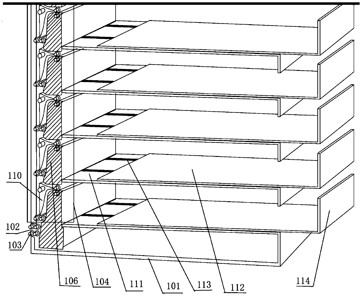
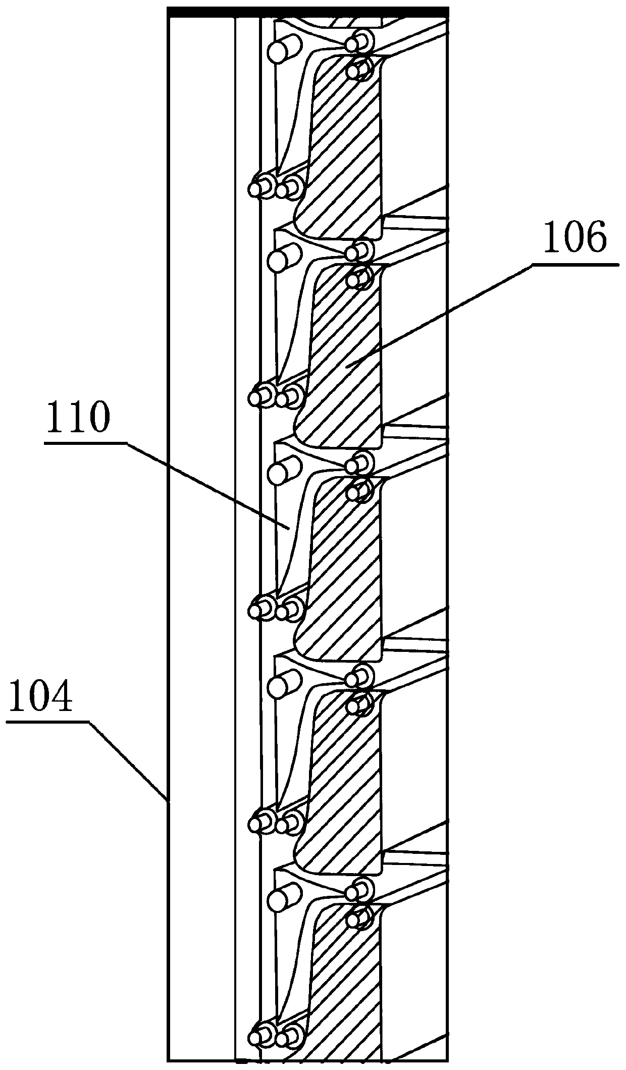
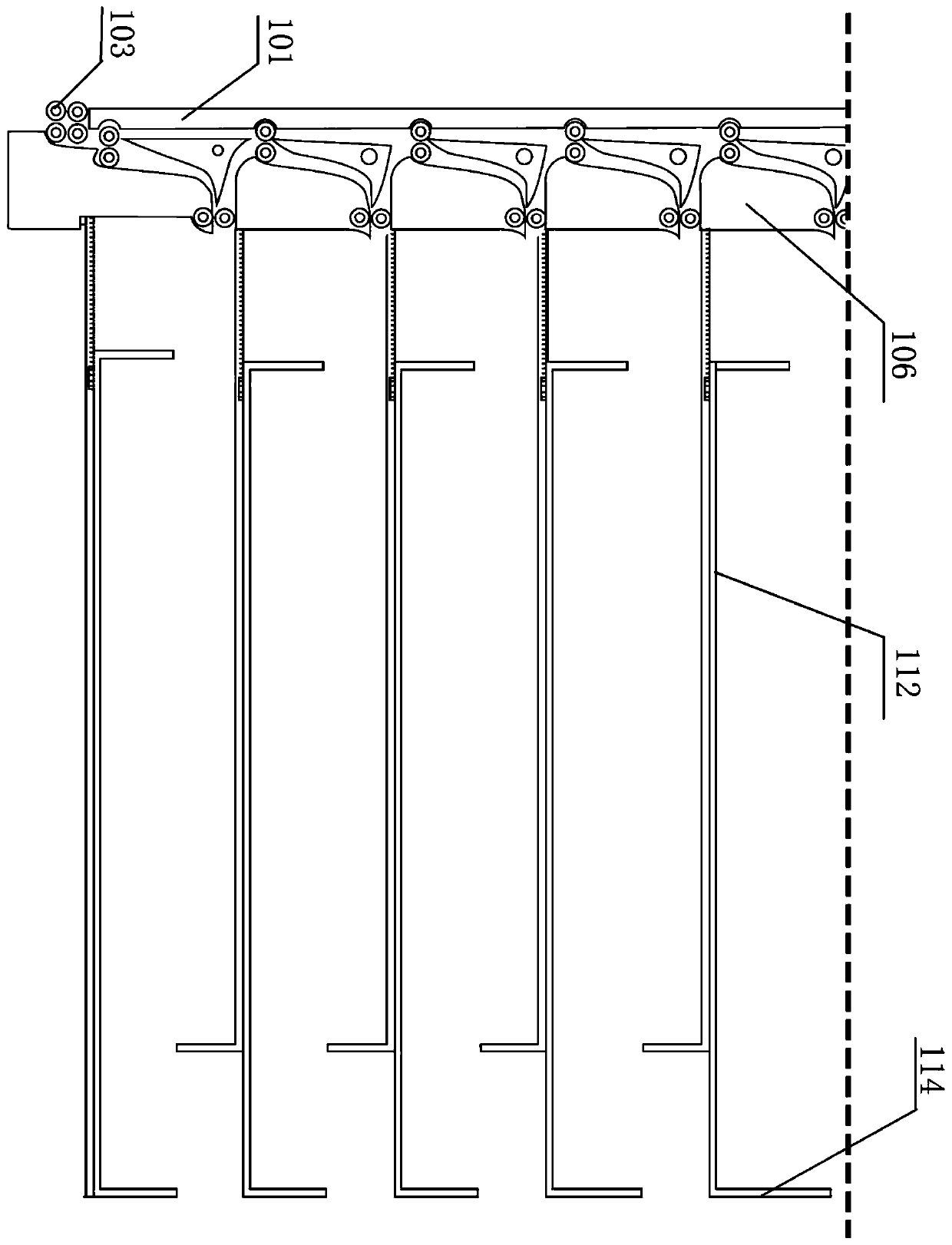
[0076] Embodiment 1: see Figure 1 to Figure 4 and Figure 13 , a multi-layer roller type automatic binding storage box, including a box body 101, the box body 101 includes a left end face, a right end face, a front side and a rear side, and the bottom of the left end face is horizontally provided with a strip-shaped paper feed Port 102, the right end face is open, and the paper inlet 102 is provided with a set of paper feed drive rollers 103, and a multi-layer transmission mechanism 104 is provided near the left end surface of the box body 101, and the multi-layer transmission mechanism 104 includes Several first single-layer conveying mechanisms 105 that are uniformly arranged from top to bottom, said first single-layer conveying mechanism 105 includes a support frame 106, a vertical conveying roller set 108 for vertically conveying paper, for A set of horizontal transfer rollers 109 and a guide mechanism 110 for horizontal transfer of paper;

[0077] The support frame 106...

Embodiment 2

[0091] Example 2: see Figure 1-Figure 8 , Figure 12 , Figure 13 . In Embodiment 2, on the basis of Embodiment 1, a side binding layer is added. That is, the function of multi-layer storage + side binding. The structure of multi-layer storage is the same as that in Embodiment 1. The structure of the side binding layer is specifically Figure 7 and Figure 8 , in this embodiment, not only a multi-layer storage area is provided in the box body 101, but also a side-side binding layer is provided;

[0092] The side binding layer includes a second horizontal base plate 201 and a second single-layer conveying mechanism 202, the second horizontal base plate 201 is the same in shape and size as the first horizontal plate, is located directly below the first horizontal base plate 111, and includes a second left edge, The second right edge, the second front edge and the second rear edge, the second single-layer conveying mechanism 202 is the same as the first single-layer conve...

Embodiment 3

[0106] Embodiment 3: see Figure 1 to Figure 13 , a multi-layer roller type automatic binding storage box, including a box body 101, the box body 101 includes a left end face, a right end face, a front side and a rear side, and the bottom of the left end face is horizontally provided with a strip-shaped paper feed mouth 102, the right end surface is open, the paper inlet 102 is provided with a group of paper feed drive rollers 103, and a multi-layer transmission mechanism 104 is arranged in the box body 101 close to the left end surface, and the multi-layer transmission mechanism 104 It includes several first single-layer conveying mechanisms 105 uniformly arranged from top to bottom, and the first single-layer conveying mechanism 105 includes a support frame 106, a vertical conveying roller set 108 for vertically conveying paper, A set of horizontal conveying rollers 109 and a guide mechanism 110 for conveying the paper horizontally;

[0107] The support frame 106 includes a...


PUM


Abstract

The invention discloses a multilayer rolling shaft type automatic binding storage box. The multilayer rolling shaft type automatic binding storage box comprises a box body, wherein the box body comprises a left end surface, a right end surface, a front side surface and a rear side surface; a long strip-shaped paper inlet is horizontally formed in the bottom of the left end surface, the right end surface is opened, a paper feeding opening is provided with a group of paper feeding transmission rolling shafts, a multilayer conveying mechanism is arranged at the position, close to the left end surface, of the box body, and a multi-layer storage layer, a side seam binding layer and a center joint binding layer are further arranged in the box body from top to bottom. According to the multilayerrolling shaft type automatic binding storage box, paper can be conveyed to different functional layers for different processing, and the paper is finally transferred to the storage layer for storage,so that printing files can be bound, classified and stored. In addition, the multi-layer storage layer, the edge seam binding layer and the center joint binding layer are correspondingly improved, themultilayer rolling shaft type automatic binding storage box is more flexible after improvement, and the expansibility is high.

Description

technical field [0001] The invention relates to a binding storage box, in particular to a multi-layer roller type automatic binding storage box. Background technique [0002] As one of the most important output devices of various computers, the printer has been greatly developed with the development of computer technology and the increasingly perfect user needs. Especially in recent years, printer technology has made great progress, and various new and practical printers have emerged as the times require. Today's printers are fast, effective, and even have the function of cloud printing. [0003] For example, the paper with the article number 1001-2265 (2015) 10-0150-04, <Research on Cloud Printing Architecture and Its Key Technologies [J]>, combines machine tool and automation control technology to build an embedded cloud printing platform. But this technology also always has the following two drawbacks. [0004] First of all, during the peak period, a large number...

Claims


Application Information

Patent Timeline
Patent Type & Authority Applications(China)
IPC IPC(8): B65H37/04B65H31/02B65H29/20B65H29/52
CPCB65H37/04B65H31/02B65H29/20B65H29/52B65H2701/1131
Inventor 罗耀耀杨宇航张伟昝立宇李代杰马晓凤罗晓雨曾晓玉
Owner CHENGDU UNIVERSITY OF TECHNOLOGY
Why Eureka
Try Eureka