
A heat pipe heating mechanism for a position-movable cable copper wire annealing equipment

A technology for moving cables and annealing equipment, which is applied to heat treatment equipment, heat treatment furnaces, furnaces, etc., can solve the problems of inability to continuously anneal online, short annealing cycle, and unadjustable heating tubes, so as to ensure normal annealing, tension and The effect of accurate position

Active Publication Date: 2020-12-08
常州市东腾金属热处理有限公司
View PDF8 Cites 0 Cited by
  • Summary
  • Abstract
  • Description
  • Claims
  • Application Information

AI Technical Summary

Problems solved by technology

[0003] In the existing annealing furnace, it is generally composed of a furnace body. It generally places the coiled copper rod in the furnace body for annealing and heating. longer
[0004] Therefore, there is a method of heating and annealing with copper rods, copper wires or aluminum rods over heating tubes. The annealing cycle is short, and the position of the existing heating tubes cannot be adjusted, so that it must be installed with the winding mechanism and the retracting tube. Corresponding to the winding mechanism, it increases the difficulty of installation, and when the winding mechanism and the winding mechanism are offset during use, it will also affect the conveying and heating effect of the copper rod, copper wire or aluminum rod

Method used


Image

  • A heat pipe heating mechanism for a position-movable cable copper wire annealing equipment
  • A heat pipe heating mechanism for a position-movable cable copper wire annealing equipment
  • A heat pipe heating mechanism for a position-movable cable copper wire annealing equipment

Examples


Embodiment

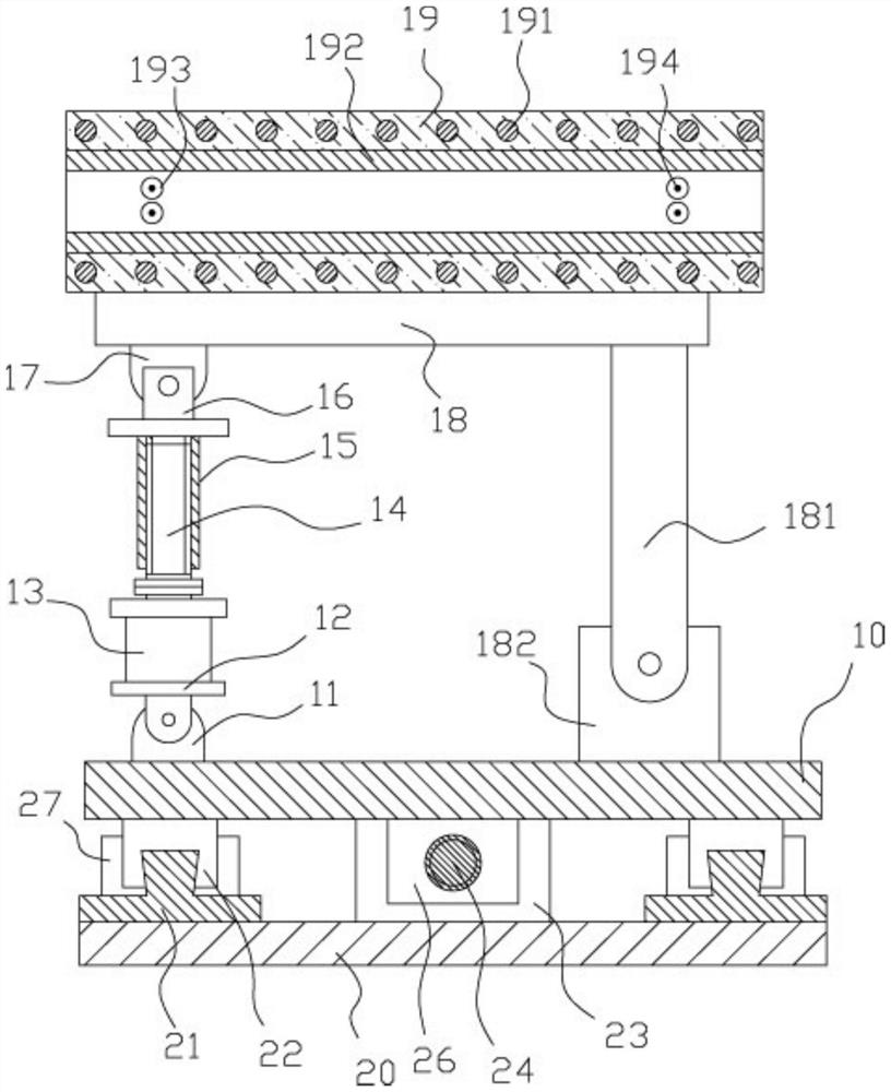
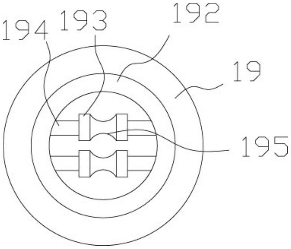
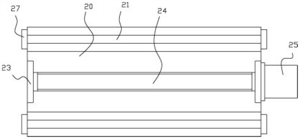
[0022] Example: see Figure 1 to Figure 3 As shown, a heat pipe heating mechanism for annealing equipment for cables and copper wires with movable positions includes a base 10 and a movable bottom plate 20. Guide rails 21 are fixed on the left and right sides of the top surface of the movable bottom plate 20, and the base 10 is in the Above the guide track 21, the left and right parts of the bottom surface of the base 10 are fixed with elongated moving sliders 22, and the upper protruding strips of the guide track 21 are inserted into the chute that the bottom surface of the elongated moving slider 22 has. , the middle front end and the rear end of the top surface of the mobile base plate 20 are fixed with a connecting vertical plate 23, and the two ends of the laterally moving screw rod 24 are hinged on two connecting vertical plates 23 through bearings, one of which connects the vertical plate 23 Main moving motor 25 is fixed on the outer wall, the output shaft of main movin...


PUM


Abstract

The invention discloses a heat pipe heating mechanism of position-movable cable copper wire annealing equipment. The heating mechanism comprises a base and a movable bottom plate, wherein guide railsare fixed on the left side and the right side of the top surface of the movable bottom plate, and the base is located above the guide rails; long-shaped movable sliding blocks are fixed on the left part and the right part of the bottom surface of the base, and upper protruding strips of the guide rails are inserted into sliding grooves in the bottom surface of the long-shaped movable sliding blocks in an inserted mode; and connecting vertical plates are fixedly arranged at the front end and the rear end of the middle of the top surface of the movable bottom plate, and the two ends of a transverse moving screw rod are hinged to the two connecting vertical plates through bearings. The heat pipe heating mechanism can be installed between a winding mechanism and a rolling mechanism, a heatingcylinder body can be inclined at an angle and can move forward and backward at any time, it is guaranteed that the heating cylinder body corresponds to the winding mechanism and the rolling mechanismin position, so that the tension degree and the position of copper wires during annealing conveying are ensured to be accurate, and conveying and annealing are guaranteed to be normal.

Description

technical field [0001] The invention relates to the technical field of cable equipment, in particular to a heat pipe heating mechanism of an annealing equipment for copper wires with movable positions. Background technique [0002] Copper rods and aluminum rods will harden and become brittle during the drawing process on the wire drawing machine. In order to restore the plasticity of the single wire and maintain good electrical properties, it is necessary to heat-treat the wire at a certain temperature; [0003] In the existing annealing furnace, it is generally composed of a furnace body. It generally places the coiled copper rod in the furnace body for annealing and heating. longer. [0004] Therefore, there is a method of heating and annealing with copper rods, copper wires or aluminum rods over heating tubes. The annealing cycle is short, and the position of the existing heating tubes cannot be adjusted, so that it must be installed with the winding mechanism and the re...

Claims


Application Information

Patent Timeline
Patent Type & Authority Patents(China)
IPC IPC(8): C21D1/26C21D9/56C21D9/68C22F1/08
CPCC21D1/26C21D9/564C21D9/68C22F1/08
Inventor 黄红兵
Owner 常州市东腾金属热处理有限公司
Learn More