
Reduced pressurization shift within diaphragm pump cavity

A technology of diaphragms and compartments, applied to components, pumps, pump elements, etc. of pumping devices for elastic fluids, which can solve expensive and time-consuming problems

Active Publication Date: 2019-10-18
GRACO INC
View PDF5 Cites 0 Cited by
  • Summary
  • Abstract
  • Description
  • Claims
  • Application Information

AI Technical Summary

Problems solved by technology

In this case, the air-driven double displacement pump must be completely disassembled and cleaned, which is a relatively time-consuming and expensive process

Method used


Image

  • Reduced pressurization shift within diaphragm pump cavity
  • Reduced pressurization shift within diaphragm pump cavity
  • Reduced pressurization shift within diaphragm pump cavity

Examples


Embodiment Construction

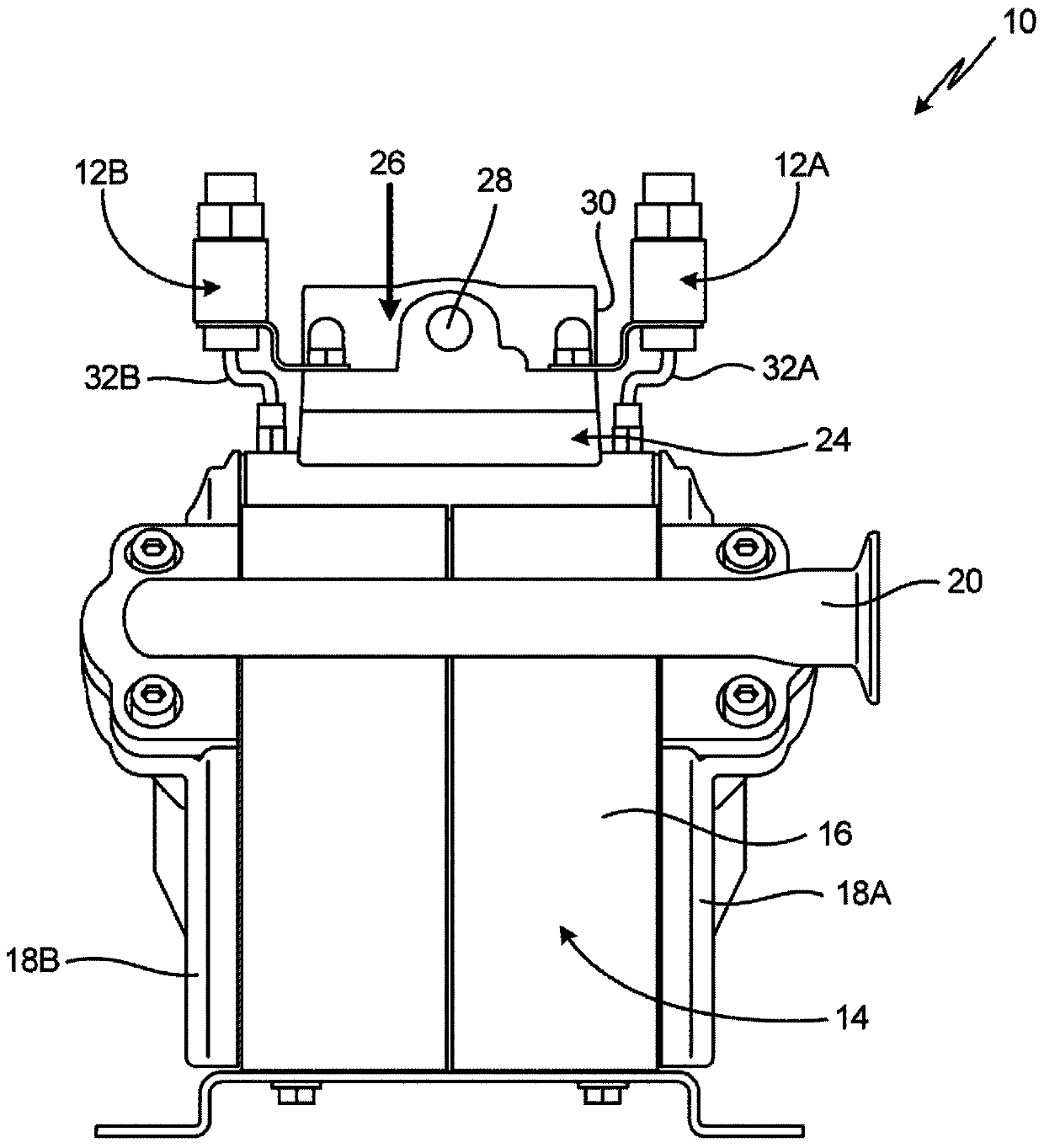
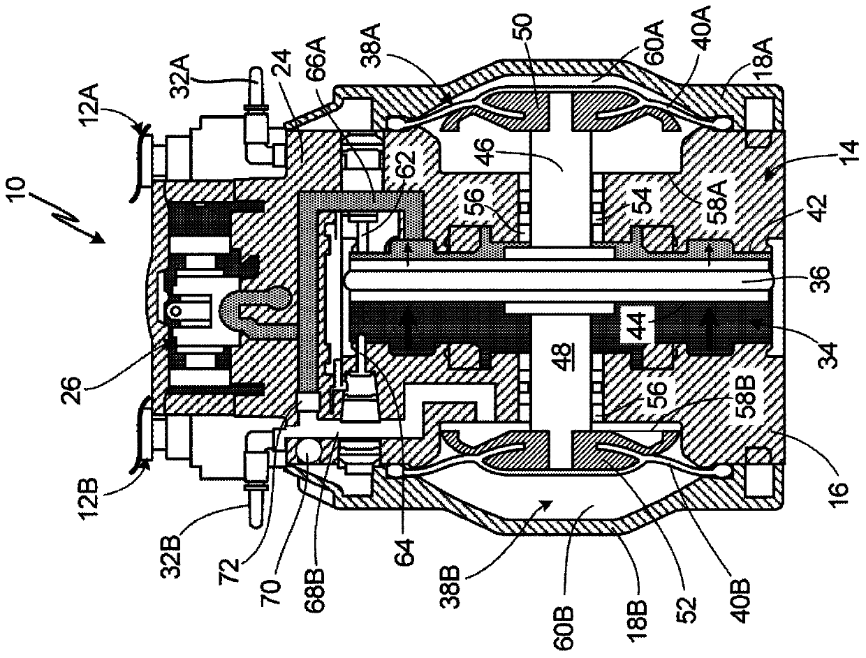
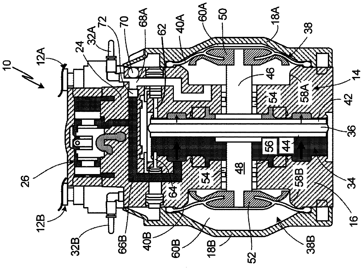
[0039]The present disclosure relates to a positive displacement pump having a first diaphragm and a second diaphragm for moving a working fluid through the positive displacement pump. The first and second diaphragms are actuated by an air motor piston housed within the air motor chamber. The air motor piston and air motor chamber are fluidly disconnected from the first and second diaphragms such that working fluid cannot reach the air motor chamber if the first or second diaphragm ruptures. In the event of a rupture of one of the first and second diaphragms, only a portion of the positive displacement pump must be disassembled and cleaned since the air motor chamber is fluidly isolated from the first and second diaphragms. The cavity behind the first and second diaphragms is vented through at least one breathing valve. The breather valve allows air to escape from the chamber when air pressure builds up inside the chamber, but is configured to prevent working fluid from escapi...


PUM


Abstract

A positive displacement pump includes a housing surrounding a drive chamber and a diaphragm compartment. A drive element is inside the drive chamber. A diaphragm is inside the diaphragm compartment and divides the diaphragm compartment into a fluid chamber and a cavity. A shaft connects the drive element and the diaphragm. A breather valve is fluidically connected to the cavity and is configured to allow air to exit the cavity. The cavity is fluidically disconnected from the drive chamber.

Description

[0001] Cross References to Related Applications [0002] This application claims U.S. Provisional Serial No. 62 / 651,552, "Reduced Pressurized Displacement in Diaphragm Pump Cavities," filed April 2, 2018, by Jason J. Willoughby and David M. Behrens application, the disclosure of which is hereby incorporated in its entirety. technical field [0003] The present disclosure relates generally to positive displacement pumps, and more particularly to positive displacement pumps with diaphragms. Background technique [0004] Positive displacement pumps can be air driven, electrically driven or hydraulically driven. Air-driven double displacement pumps typically employ a diaphragm to move a working fluid such as paint. In an air-driven double displacement pump, two diaphragms are connected by a shaft, and compressed air does work in the pump. Compressed air is applied to one of the two diaphragm compartments associated with the respective diaphragm. When compressed air is applie...

Claims


Application Information

Patent Timeline
IPC IPC(8): F04B23/04F04B43/073F16K15/04F16K15/18F16K1/14
CPCF04B43/073F04B23/04F16K15/044F16K1/14F16K15/1823F04B39/14F04B43/0081F04B43/0736F04B53/06F04B53/22F04B45/0533F04B45/0536F04B45/043F04B45/047F04B45/053F04B53/10F05B2240/57F05B2210/12F04B53/1002F04B43/06
Inventor 詹森·J·威洛比大卫·M·贝伦斯
Owner GRACO INC
Learn More