
Rotational flow atomization device achieving fractional combustion

A staged combustion and atomization device technology, applied in combustion chambers, combustion methods, combustion equipment, etc., can solve the problems of easy flameout, reduced combustion efficiency, and high exhaust pollution, so as to improve the effect of oil and gas mixing and solve the problem of stable combustion Poor performance, solve the effect of high exhaust pollution

Active Publication Date: 2019-10-18
AECC SHENYANG ENGINE RES INST
View PDF6 Cites 1 Cited by
  • Summary
  • Abstract
  • Description
  • Claims
  • Application Information

AI Technical Summary

Problems solved by technology

The main disadvantages of the existing technical solutions are as follows: when the engine is in a large working condition, the pressure in the main combustion chamber is high, the aerodynamic force is enhanced, and the resistance of the oil droplets in the airflow increases, so that the fuel near the nozzle is relatively concentrated, causing smoke, carbon deposits, Combustion efficiency reduction and other issues; when the engine is in a small working condition, the fuel supply to the main combustion chamber is low, the atomization level of the nozzle is poor, the combustion stability is poor, and it is prone to flameout; it is impossible to achieve good atomization and combustion under all working conditions Oil and gas matching, high exhaust pollution, does not meet the increasingly stringent aero engine exhaust pollution restrictions

Method used


Image

  • Rotational flow atomization device achieving fractional combustion
  • Rotational flow atomization device achieving fractional combustion
  • Rotational flow atomization device achieving fractional combustion

Examples


Embodiment Construction

[0033] In order to make the purpose, technical solution and advantages of the application more clear, the technical solution in the embodiment of the application will be described in more detail below in conjunction with the drawings in the embodiment of the application. In the drawings, the same or similar reference numerals denote the same or similar elements or elements having the same or similar functions throughout. The described embodiments are some, but not all, embodiments of the application. The embodiments described below by referring to the figures are exemplary, and are intended to explain the present application, and should not be construed as limiting the present application. Based on the embodiments in this application, all other embodiments obtained by persons of ordinary skill in the art without creative efforts fall within the protection scope of this application. Embodiments of the present application will be described in detail below in conjunction with th...


PUM


Abstract

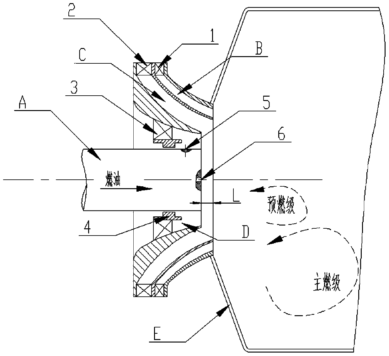
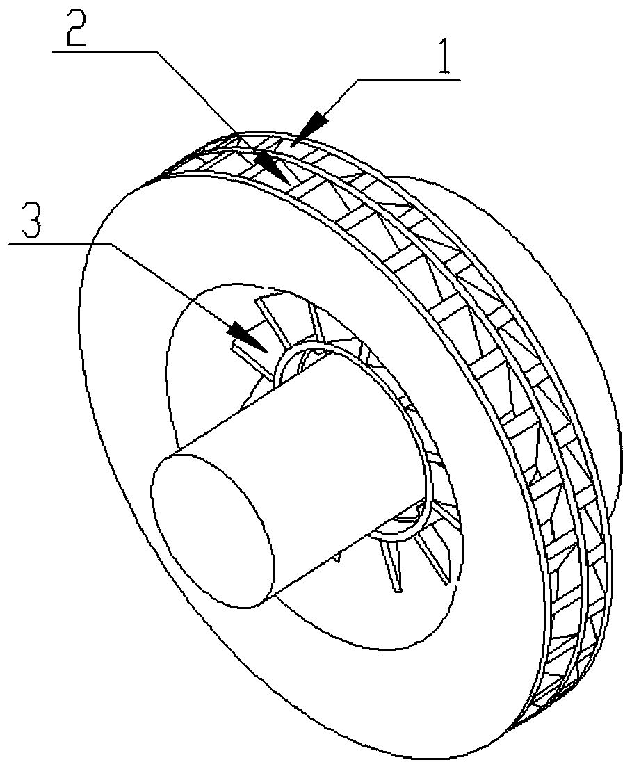
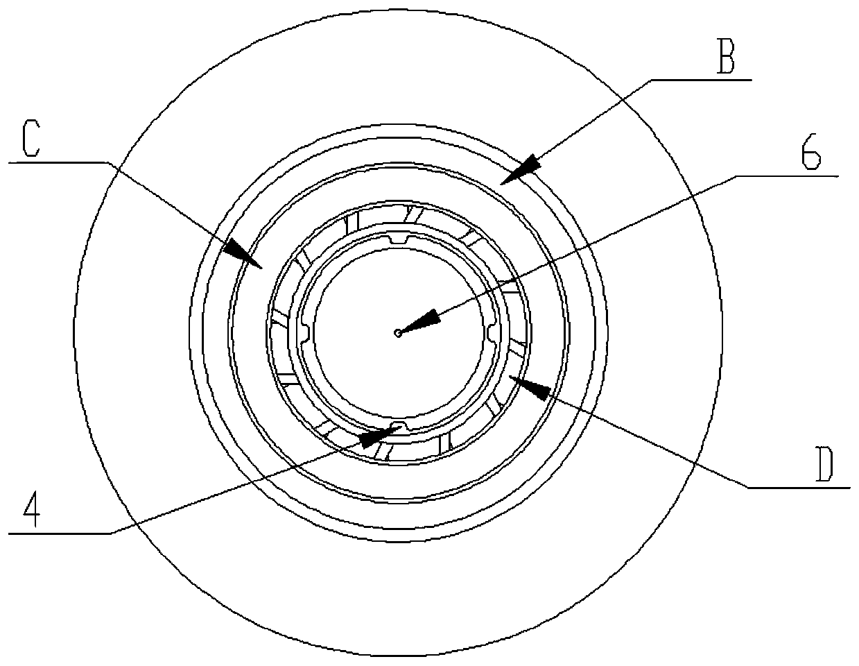
The invention belongs to the field of design of aero-engine main combustion chambers, and particularly relates to a rotational flow atomization device achieving fractional combustion. The rotational flow atomization device comprises an outer swirler, a middle swirler, an inner swirler, an inner supporting plate and a nozzle A. One end of a first wall plate of the outer swirler is connected with aflame tube E. The middle swirler comprises a second wall plate and second blades. The middle swirler is embedded in the outer swirler. The second wall plate is connected with first blades. An outer airflow channel B is formed between the second wall plate and the first wall plate. The inner swirler comprises a third wall plate and third blades and is embedded in the middle swirler. The third wallplate is connected with the second blades, and a middle airflow channel C is formed between the third wall plate and the second wall plate. The inner supporting plate is embedded in the inner swirler,the inner supporting plate is connected with the third blades, and an inner airflow channel D is formed between the inner supporting plate and the third wall plate. The nozzle A is embedded in the inner supporting plate and is in clearance fit with the inner supporting plate, main spray openings are formed in the side wall of the nozzle A, and an auxiliary spray opening is formed in the end of the nozzle A.

Description

technical field [0001] The application belongs to the design field of the main combustion chamber of an aero-engine, and in particular relates to a swirl atomization device for staged combustion. Background technique [0002] The swirl atomization device at the head of the flame tube in the main combustion chamber of an aero-engine generally adopts the structural form of a single-stage or multi-stage swirler combined with a centrifugal pressure atomization nozzle. [0003] In the prior art, the swirling atomization device at the head of the flame tube in the main combustion chamber is composed of a fuel nozzle, a main swirler and a secondary swirler, and the nozzle can be a single oil circuit centrifugal pressure atomization nozzle or a double oil circuit centrifugal type Pressure atomizing nozzles. The swirler is used to create a recirculation zone in the flame tube to ensure stable and efficient combustion. The atomization of fuel is mainly achieved by the pressure differ...

Claims


Application Information

Patent Timeline
Patent Type & Authority Applications(China)
IPC IPC(8): F23R3/38
CPCF23R3/38
Inventor 白瑞强郭舒闫东博赵传亮
Owner AECC SHENYANG ENGINE RES INST
Learn More