Clip-on ammeter

A clamp-type ammeter and clamp-type technology are applied in the field of ammeters, which can solve the problems of pollution and a large amount of dust, and achieve the effects of reducing environmental pollution, reducing dust, and having a simple and compact structure.

Inactive Publication Date: 2019-10-18
STATE GRID CORP OF CHINA +1
View PDF5 Cites 1 Cited by
  • Summary
  • Abstract
  • Description
  • Claims
  • Application Information

AI Technical Summary

Problems solved by technology

[0002] Application number: CN201410728344.4 discloses a device capable of blowing off dust to facilitate maintenance. We found that this device will generate a lot of dust while blowing dust, causing pollution

Method used


Image

  • Clip-on ammeter

Examples


Embodiment Construction

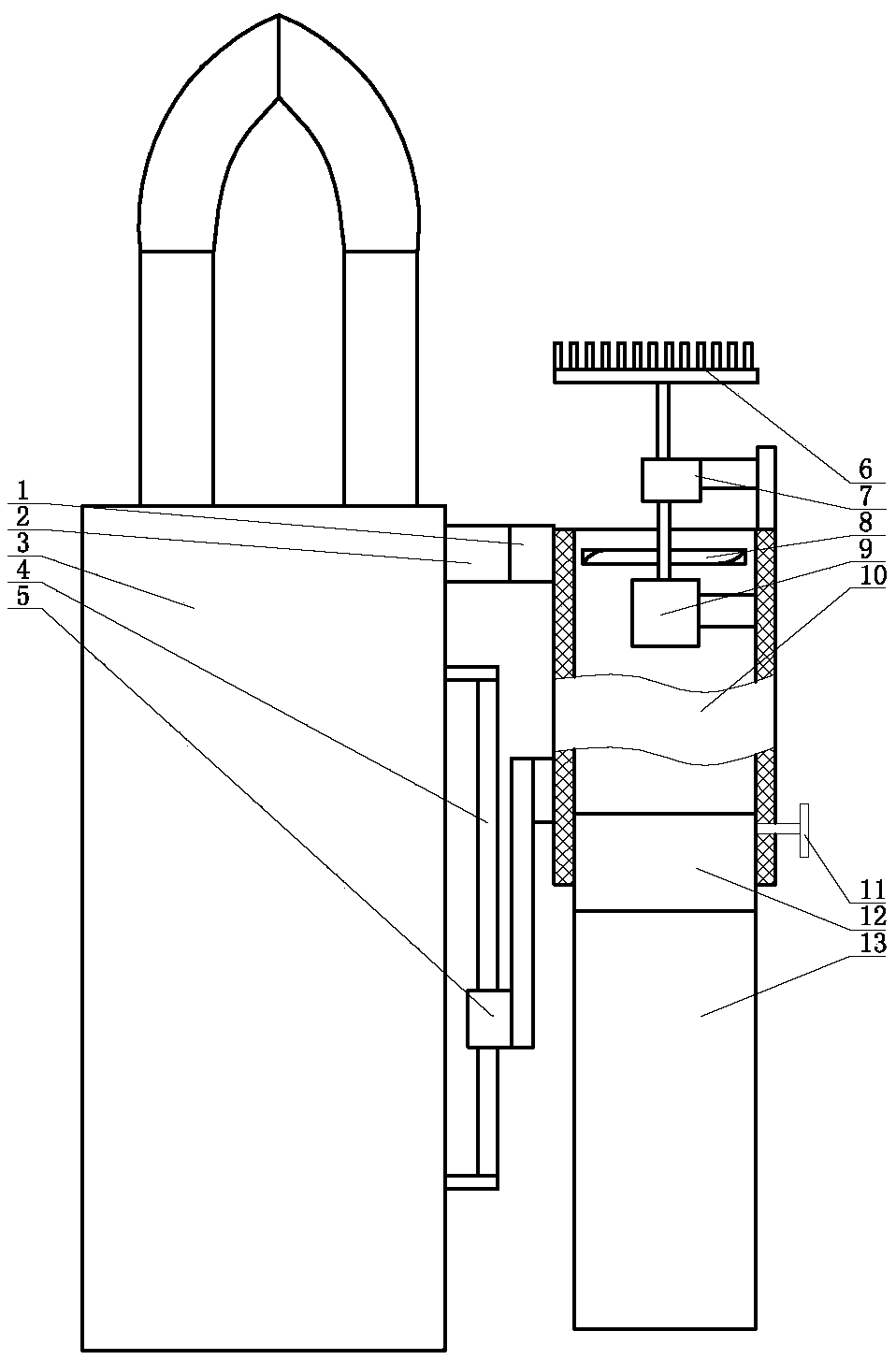
[0012] Preferred embodiments of the present invention will be described below in conjunction with the accompanying drawings.

[0013] Clamp-on ammeters, such as figure 1 As shown, the clamp multimeter 3 is included, and a fixed tube 10 is installed on one side of the clamp multimeter 3. The fixed tube 10 is a tubular structure, and one end of the fixed tube 10 is connected to a cloth bag 13, and the cloth bag 13 is a shell made of filter cloth with an open end. structure, the opening of the cloth bag 13 is docked with the opening of one end of the fixed pipe 10, the inside of the fixed pipe 10 is connected to the motor 9 and the gearbox 7, the middle part of the output shaft of the motor 9 is connected to the fan blade 8, and the end of the output shaft of the motor 9 is connected to the gearbox 7 The end of the input shaft of the gearbox 7 is connected to the end of the output shaft of the gearbox 7 and the brush 6 is connected.

[0014] The present invention utilizes gearbo...


PUM


Abstract

The invention discloses a clip-on ammeter. The clip-on ammeter includes a clip-on multimeter. A fixed pipe is installed on one side of the clip-on multimeter. The fixed pipe is a pipe-shaped structure. One end of the fixed pipe is connected to a cloth bag. The cloth bag is a shell structure that has an opening at one end and made of filter cloth. An opening of the cloth bag is abutted with the opening at one end of the fixed pipe. By combining a transmission, a blade and a brush, the motor can drive the blade to rotate to suck dust into the fixed pipe and the cloth bag. In the meanwhile, the motor can drive an input shaft of the transmission to rotate, and after the transmission decelerates, the brush is driven to rotate at a relatively low speed, thus a user can brush the dust off by using the brush conveniently, and the blade can suck the dust.

Description

technical field [0001] The invention relates to an ammeter, more precisely a clamp ammeter. Background technique [0002] Application number: CN201410728344.4 discloses a device capable of blowing off dust to facilitate maintenance. We found that this device will generate a large amount of dust while blowing dust, causing pollution. Contents of the invention [0003] The purpose of the present invention is to provide a clamp ammeter, which can combine the gearbox, the fan blade, the motor and the brush. The motor can drive the fan blade to rotate and suck the dust into the fixed pipe and the inside of the cloth bag. At the same time, the motor can drive the gearbox. The input shaft rotates, and after the gearbox decelerates, the brush is driven to rotate at a slower speed, so that the user can use the brush to brush off the dust, and the fan blades can absorb the dust. [0004] In order to achieve the above object, the present invention is achieved through the following t...

Claims


Application Information

Patent Timeline
Patent Type & Authority Applications(China)
IPC IPC(8): G01R15/00G01R19/00B08B1/00
CPCB08B1/002G01R15/00G01R19/00
Inventor 王灿光王新文李秀占杨备战李锦飞贾伟陈美玲高康健王承志李萍萍孙煜皓刘秀忠
Owner STATE GRID CORP OF CHINA
Why Eureka
Try Eureka