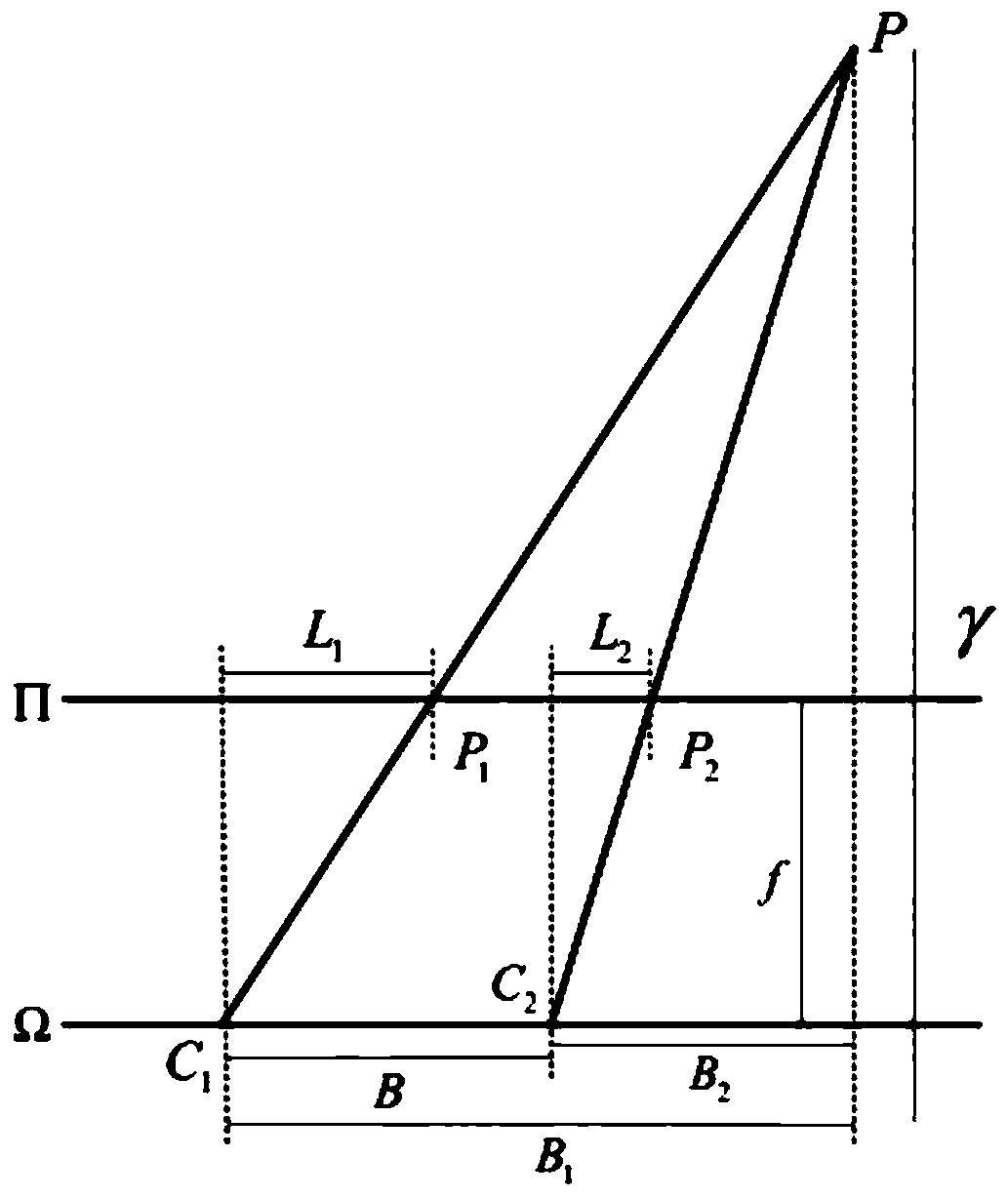
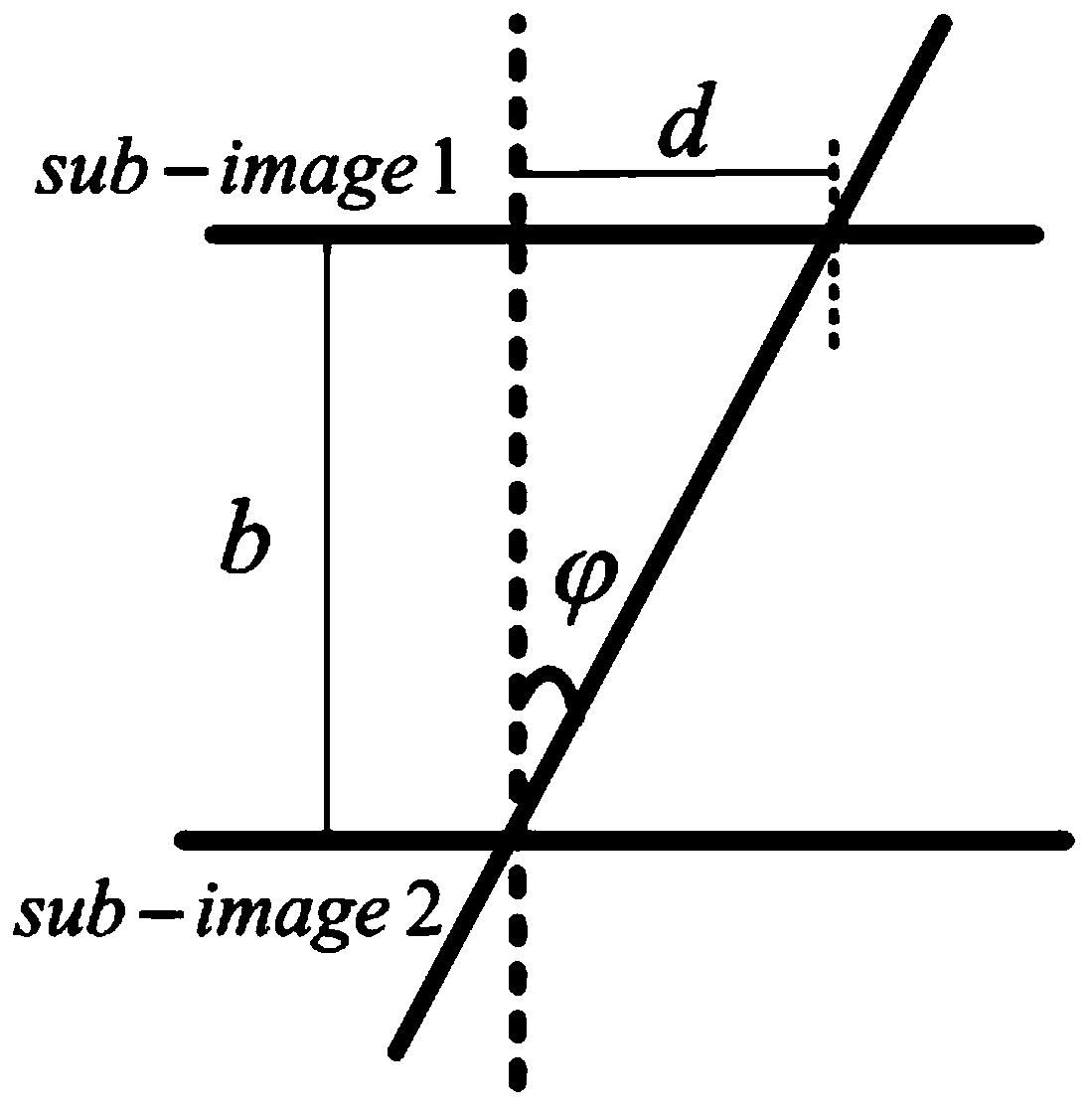
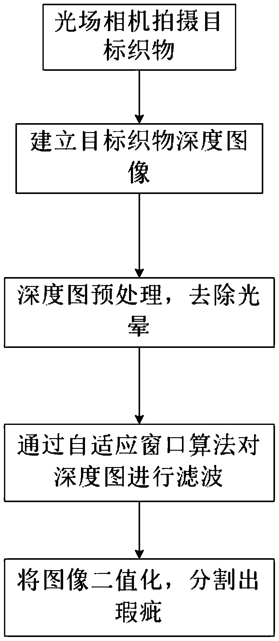
Fabric flaw detection method based on light field camera depth information extraction

A technology of light field camera and depth information, which is applied in image data processing, instrumentation, computing, etc., can solve problems such as vignetting effect, not well resolved, and complex target influence, so as to avoid vignetting effect Effect

Active Publication Date: 2019-10-18
WUHAN TEXTILE UNIV
View PDF10 Cites 10 Cited by
  • Summary
  • Abstract
  • Description
  • Claims
  • Application Information

AI Technical Summary

Problems solved by technology

Most of the existing light field camera depth processing technologies deal with some relatively large objects, or the shooting target is far away from the imaging surface, such as the depth processing of light field cameras used for statues and Lego cars, because the light field camera microlens array Because of the vignetting effect, it will have a great impact on close-range high-precision and high-texture complexity targets, such as fabric textures, etc.
The current light field camera depth map construction technology has been very developed, and the light field camera can be used to realize 3D reconstruction very clearly, but the vignetting effect of the light field camera has not been well solved yet.
Existing solutions are all estimated based on the particularity of the object, and the estimated results cannot be used in the detection field

Method used


Image

  • Fabric flaw detection method based on light field camera depth information extraction
  • Fabric flaw detection method based on light field camera depth information extraction
  • Fabric flaw detection method based on light field camera depth information extraction

Examples


Embodiment

[0042] The present invention comprises the following steps:

[0043] Step 1: Collect a set of multi-view images with a light field camera.

[0044]Step 1.1: Shoot the target fabric with a light field camera in a uniform light field, extract the RAW file and white image file in the light field camera, decode the extracted RAW file first, and then color correct it, which needs to use Matlab light field toolkit, this toolkit is developed by D.G.Dansereau et al. Currently, there are two versions of toolbox0.3 and toolbox0.4. What is used in this embodiment is toolbox0.4, and the white image file will be used when decoding the image , each light field camera will have its own white image file, the toolkit reads the WhiteImagesDataBase mapping table, and the toolkit selects the most suitable white image and microlens grid model to obtain the light field image in Bayer format. Then perform frequency domain filtering on the image to perform demosaic operation on the image to obtain a...


PUM


Abstract

The invention relates to a fabric flaw detection method based on light field camera depth information extraction. The fabric flaw detection method can be applied to the field of fabric detection and is a method for detecting fabric flaws from a three-dimensional space. The fabric flaw detection method utilizes a light field camera to generate a multi-view image sequence of a target fabric, replaces a parallax estimation depth value by a slope, and obtains a depth map by using a sub-pixel offset method. In order to avoid vignetting effect interference of the micro lens of the light field camera, the fabric flaw detection method extracts a weak influence area, and performs noise reduction processing on the weak influence area. According to the fabric flaw detection method, an image adaptivewindow filtering noise reduction method is used for noise reduction; errors caused by too large and too small median filtering windows are effectively avoided; and finally, binarization is carried outto obtain a segmentation image. When the fabric flaw detection method is used for treating the fabric, the defective part of the fabric can be effectively detected.

Description

technical field [0001] The invention relates to a method for detecting fabric defects, especially the processing, extraction and detection of three-dimensional depth information of fabrics Background technique [0002] The earliest depth processing is to use the camera array to obtain the parallax. The light field camera replaces the complex camera array with the main lens and the microlens array. One camera can realize the function of a camera array to obtain the depth. Most of the existing light field camera depth processing technologies deal with some relatively large objects, or the shooting target is far away from the imaging surface, such as the depth processing of light field cameras used for statues and Lego cars, because the light field camera microlens array Because of the vignetting effect, there will be a vignetting effect, which will have a great impact on close-range high-precision and high-texture complexity targets, such as fabric textures. The current light...

Claims


Application Information

Patent Timeline
Patent Type & Authority Applications(China)
IPC IPC(8): G06T7/00G06T5/00G06T7/50G06T7/11G06T7/136
CPCG06T5/002G06T5/007G06T7/0004G06T2207/10052G06T2207/20132G06T2207/30124G06T7/11G06T7/136G06T7/50
Inventor 袁理程哲
Owner WUHAN TEXTILE UNIV
Why Eureka
Try Eureka