Air-blowing, cooling and dust-removal power distribution cabinet

A power distribution cabinet and power technology, which is applied in the substation/distribution device casing, electrical components, substation/switch layout details, etc. Wind, improve dust removal effect, reduce temperature effect

Active Publication Date: 2019-10-18
扬州市鸣庆电气设备有限公司
View PDF14 Cites 7 Cited by
  • Summary
  • Abstract
  • Description
  • Claims
  • Application Information

AI Technical Summary

Problems solved by technology

[0003] After the power distribution cabinet is used for a long time, a large amount of dust will enter the interior and adhere to the electronic components. If the dust is not cleaned in time, it will increase the resistance, generate a lot of heat inside, and affect the safe and normal operation of the electronic components. The existing The dust removal equipment only blows air to the inside, but due to the many internal structures, the dust is easily blocked and cannot be blown out in time, and the dust removal effect is poor

Method used


Image

  • Air-blowing, cooling and dust-removal power distribution cabinet
  • Air-blowing, cooling and dust-removal power distribution cabinet
  • Air-blowing, cooling and dust-removal power distribution cabinet

Examples


Embodiment 1

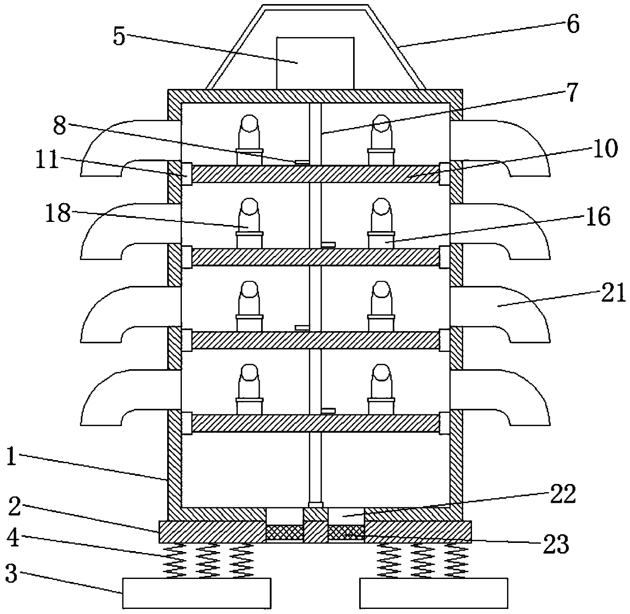
[0020] Please refer to the figure, in the embodiment of the present invention, a power distribution cabinet for blowing, cooling and dust removal includes a cabinet body 1, a base 2, a fixing seat 3 and a shock absorbing spring 4; the base 2 is fixedly welded on the cabinet body 1 At the bottom, a horizontal fixed seat 3 is provided below the base 2, and the fixed seat 3 is fixed on the ground by expansion bolts, and several shock absorbing springs 4 are fixedly installed between the base 2 and the fixed seat 3, and the shock absorbing spring 4 Connect the base 2 and the fixed seat 3 to play a role of shock absorption and buffering thereon.

[0021] A vertically downward motor 5 is fixed on the top of the cabinet 1, and a vertical shaft 7 is fixedly connected to the lower end of the output shaft of the motor 5, and the shaft 7 extends downward to the bottom of the cabinet 1 and is rotatably connected by a bearing. , the outer cover of the motor 5 is provided with a protective ...

Embodiment 2

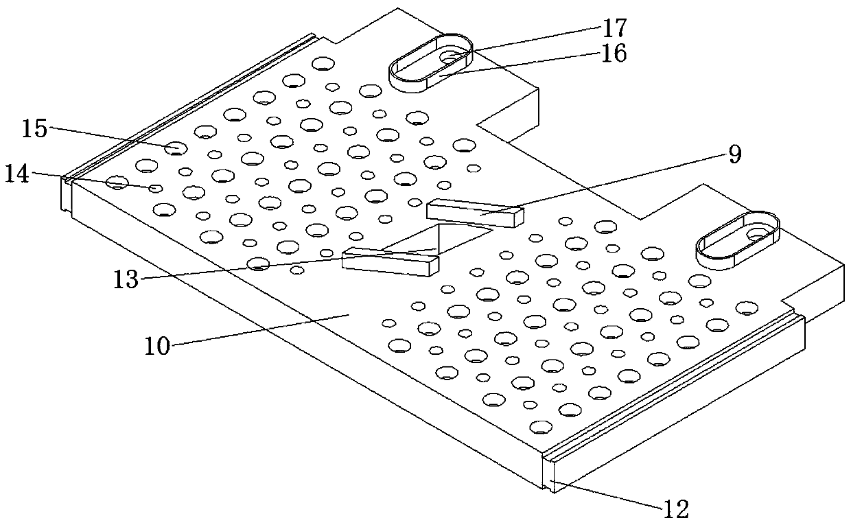
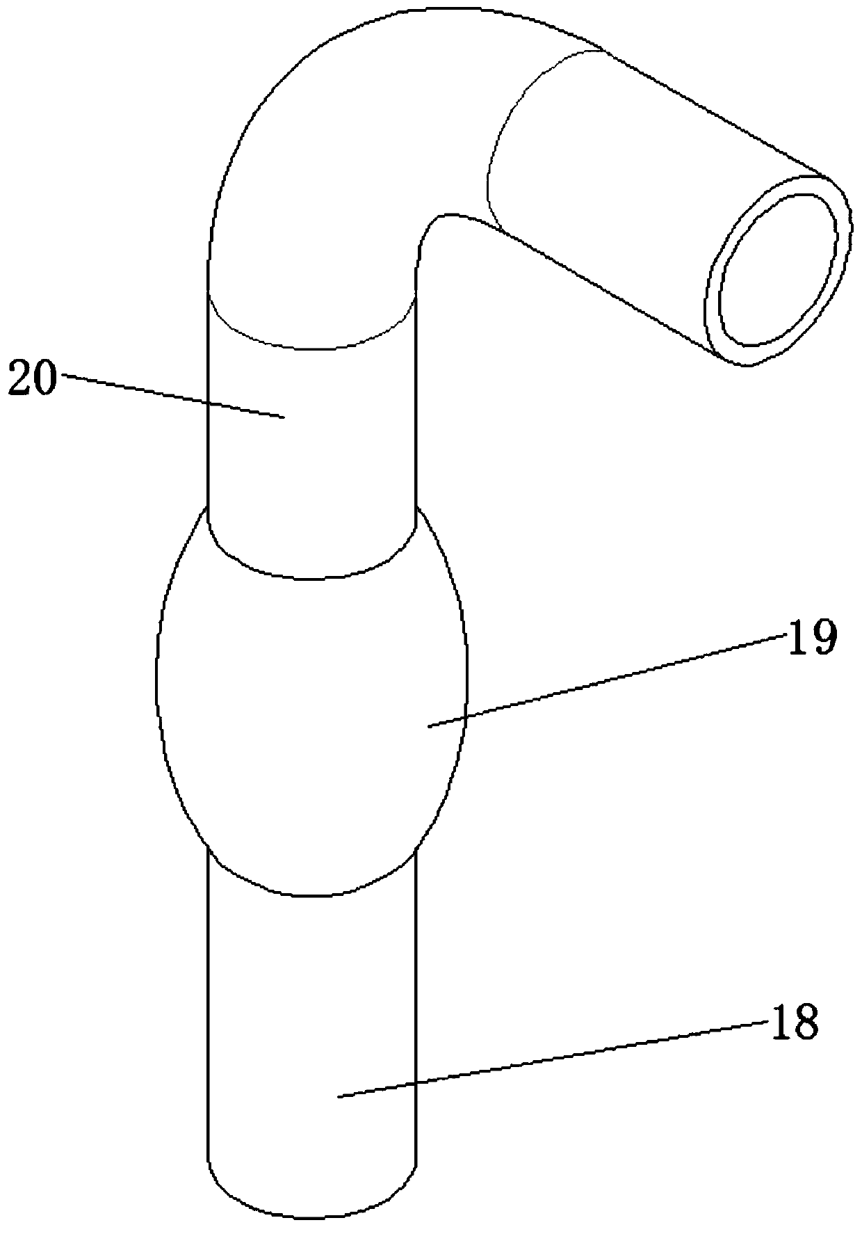
[0024] On the basis of Embodiment 1, preferably, the branch pipe 20 is provided with two, the lower end of the branch pipe 20 communicates with a vertically downward air inlet pipe 18, and the outer wall of the air inlet pipe 18 is covered with an airbag 19, And offer some holes on the side wall of the air inlet pipe 18 to communicate with the air bag 19, so that the air in the air inlet pipe 18 can enter the air bag 19 to expand the air bag 19; The upper surface of 10 is fixed with a horizontal sliding sealing groove 16, the sliding sealing groove 16 has an oval structure and is distributed along the front and rear directions, the lower end of the air inlet pipe 18 extends into the sliding sealing groove 16, and is connected with the sliding sealing groove 16. There is a gap at the bottom, and the distance is 0.2-0.4mm; a connecting hole 17 is provided on one end of the bottom in the sliding sealing groove 16, and the partition 10 is a hollow structure, and the connecting hole...


PUM


Abstract

The invention belongs to the power field and discloses an air-blowing, cooling and dust-removal power distribution cabinet. The air-blowing, cooling and dust-removal power distribution cabinet comprises a cabinet body, bases, fixing seats and damping springs; a plurality of separation plates are arranged in the cabinet body from top to bottom; horizontal sliding blocks are fixed onto the left sides and right sides of the separation plates respectively; horizontal sliding rails corresponding to the sliding blocks are fixed on the inner wall of the cabinet body; a shaft hole is formed at the center of each separation plates; a rotating shaft penetrates through the shaft holes; fixing blocks are fixedly arranged on the upper surface of each separation plate and are located at the front side and back side of the corresponding shaft hole respectively; pushing rods located above the separation plates respectively are fixed onto the side wall of the rotating shaft; and downward-facing branchpipes are arranged above each separation plate. According to the air-blowing, cooling and dust-removal power distribution cabinet of the invention, the rotating shaft is adopted to drive the pushing rods to rotate, so that the separation plates can move forwards and backwards in a horizontal direction, and therefore, electric appliance elements on the separation plates can be moved; air incoming pipes blow air downwards; connection holes which are intermittently communicated with the air incoming pipes enable the air to enter the separation plates; and the air is blown out through air blowingholes.

Description

technical field [0001] The invention relates to the field of electric power, in particular to a power distribution cabinet for blowing, cooling and dust removal. Background technique [0002] The power distribution cabinet is the final equipment of the power distribution system, and it is the general name of the motor control center. The power distribution cabinet is one of the most widely used equipment in power equipment. During power construction, many electrical components must be installed in the power distribution cabinet. In order to improve the utilization rate of the power distribution cabinet in an existing power distribution cabinet, partition boards are arranged in the power distribution cabinet. The partition boards divide the power distribution cabinet into multiple layers, and electrical components can be placed on each layer. [0003] After the power distribution cabinet is used for a long time, a large amount of dust will enter the interior and adhere to th...

Claims


Application Information

Patent Timeline
Patent Type & Authority Applications(China)
IPC IPC(8): H02B1/30H02B1/28H02B1/56H02B1/32
CPCH02B1/28H02B1/30H02B1/32H02B1/565
Inventor 许喜璇
Owner 扬州市鸣庆电气设备有限公司
Why Eureka
Try Eureka