
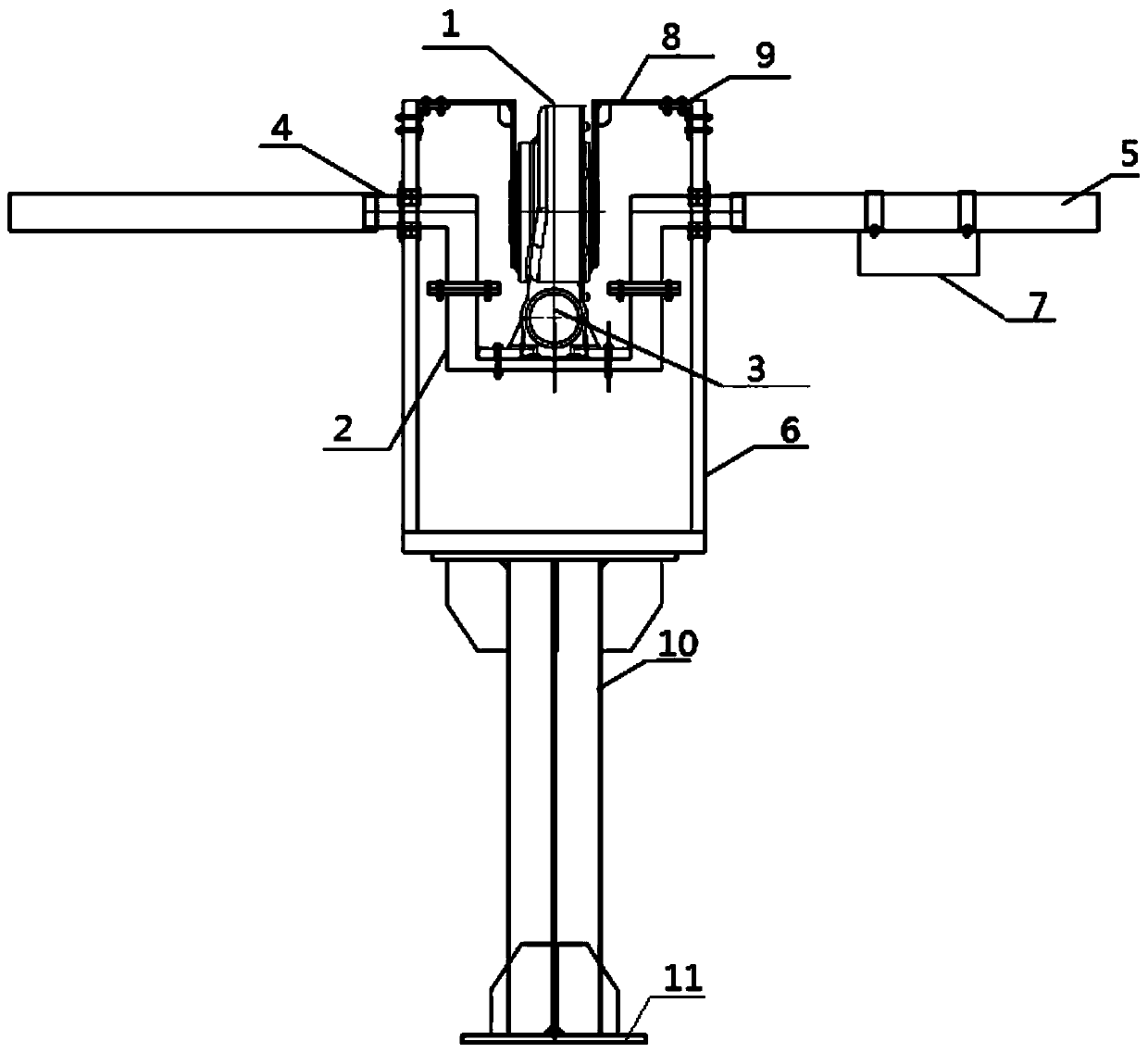
Control box follow-up type photovoltaic tracker driving assembly

A drive assembly and control box technology, applied in the direction of photovoltaic power generation, photovoltaic modules, support structures of photovoltaic modules, etc., can solve the problems of easy damage to wiring, failure to fully exert performance, and poor structural layout of photovoltaic tracker drive assemblies. Reasonable and other issues

Pending Publication Date: 2019-10-18
ZHEJIANG ZHENGTAI NEW ENERGY DEV CO LTD
View PDF0 Cites 0 Cited by
  • Summary
  • Abstract
  • Description
  • Claims
  • Application Information

AI Technical Summary

Problems solved by technology

The structure layout of the existing photovoltaic tracker drive assembly is unreasonable. The output shaft of the reducer is connected coaxially with the main shaft. It is necessary to drive the main shaft to rotate and to overcome the eccentricity caused by the asymmetric installation of the photovoltaic modules on the main shaft. The reducer Part of the output power is used to drive the main shaft to rotate, and the other part is used to balance the eccentric rotation of the main shaft. The performance has not been fully utilized, and the control box is installed on the column. It is necessary to reserve sufficient length of wiring to prevent the wiring from being wrapped around the main shaft, causing the control box Higher installation costs and easily damaged wiring
[0003] Therefore, how to solve the problem of unreasonable structural layout of the photovoltaic tracker drive assembly has become a technical problem to be solved by those skilled in the art

Method used


Image

  • Control box follow-up type photovoltaic tracker driving assembly

Examples


Embodiment Construction

[0023] The following will clearly and completely describe the technical solutions in the embodiments of the present invention with reference to the accompanying drawings in the embodiments of the present invention. Obviously, the described embodiments are only some, not all, embodiments of the present invention. Based on the embodiments of the present invention, all other embodiments obtained by persons of ordinary skill in the art without making creative efforts belong to the protection scope of the present invention.

[0024] The core of the present invention is to provide a control box follow-up photovoltaic tracker drive assembly, which improves the structural layout of the existing drive assembly, reduces the installation cost of the control box 7, avoids wiring damage, and at the same time fully utilizes the reducer 1 performance.

[0025] In order to enable those skilled in the art to better understand the solution of the present invention, the present invention will be...


PUM


Abstract

The invention discloses a control box follow-up type photovoltaic tracker driving assembly. The control box follow-up type photovoltaic tracker driving assembly comprises a speed reducer mounting seat, a speed reducer fixed to the speed reducer mounting seat and a driving motor used for driving the speed reducer to rotate; two ends of the speed reducer mounting seat are connected with a pair of crankshafts; the crankshafts connected to the two ends of the speed reducer mounting seat are respectively connected with two main shafts; the axes of the two main shafts are located on a straight line;the main shafts are provided with control boxes used for controlling the driving motor to operate; the control box follow-up type photovoltaic tracker driving assembly further comprises structure mounting seats for supporting the crankshafts to rotate; the output shaft of the speed reducer is fixedly connected with the structure mounting seats; and the crankshafts are used for balancing the eccentric distances of the main shafts. The control box follow-up type photovoltaic tracker driving assembly is reasonable in structural layout. According to the control box follow-up type photovoltaic tracker driving assembly, the performance of the speed reducer can be fully exerted, the installation cost of the control boxes is reduced, and wires are prevented from being damaged.

Description

technical field [0001] The invention relates to the technical field of photovoltaic modules, in particular to a control box follow-up photovoltaic tracker drive assembly. Background technique [0002] In photovoltaic power generation systems, in order to improve the photoelectric conversion capability, photovoltaic modules are generally set facing the direction of sunlight. Since the power generation efficiency of photovoltaic power generation is greatly affected by the angle of sunlight, a photovoltaic tracking system is installed to make the orientation of each solar panel in the photovoltaic power generation system move with the angle of sunlight, which can effectively improve the photoelectric conversion efficiency. Multiple tracking devices in a tracking system usually share a set of drive assemblies and are connected through the main shaft to transmit torque. The structure layout of the existing photovoltaic tracker drive assembly is unreasonable. The output shaft of ...

Claims


Application Information

Patent Timeline
IPC IPC(8): H02S20/32
CPCH02S20/32Y02E10/50
Inventor 陈创修李春阳罗易周承军李科庆陆川
Owner ZHEJIANG ZHENGTAI NEW ENERGY DEV CO LTD
Learn More