

Leading-end tip for catheter, and stent delivery device
A transmission device and catheter technology, applied in the direction of catheters, stents, etc., to achieve the effect of reducing irritation
- Summary
- Abstract
- Description
- Claims
- Application Information
AI Technical Summary
Problems solved by technology
Method used
Image

Examples
no. 1 approach
[0036] Hereinafter, embodiments of the present invention will be specifically described with reference to the drawings. In this embodiment, the case of indwelling a covered self-expanding stent in transgastric and transhepatic biliary drainage (EUS-BD) under the guidance of ultrasonic endoscope will be described as an example. and intrahepatic bile ducts. However, the present invention is not limited to the bypass connection between the stomach and the intrahepatic bile duct, and can be widely applied to bypass connections between the duodenum and the common bile duct, etc., or between hollow organs and other hollow organs. Condition. In addition, the present invention is not limited to the case of indwelling a stent in this way, and can be applied, for example, to bile duct drainage through the duodenal papilla (when a stent is placed in a narrow part of the common bile duct) and in a lumen other than the common bile duct. When a stent is placed in a narrow part.
[0037] ...
no. 2 approach
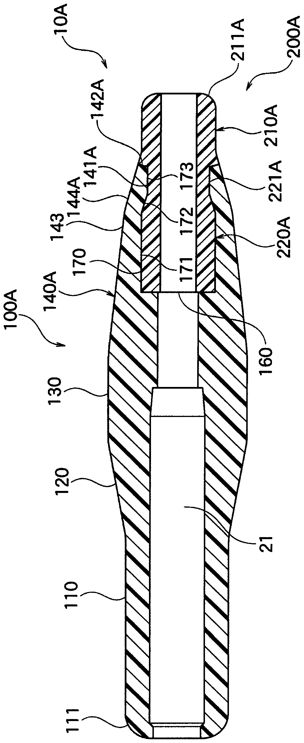
[0081] Figure 2B The distal head 10A of the present embodiment shown has the same structure and effects as those of the first embodiment except for the points shown below, and the description of the common parts will be omitted, and the common parts will be marked with a common symbol in the figure. Part reference number. Such as Figure 2B As shown, the tip 10A has a first part 100A and a second part 200A.
[0082] The first part 100A is identical to the first part 100 of the first embodiment except that it has a distal taper 140A instead of the distal taper 140 . In more detail, the distal taper 140 has an anchoring protrusion 141A. The second tapered surface 144A is formed to have an axial length shorter than that of the second tapered surface 144 in the first embodiment.
[0083] The anchoring protrusion 141A is formed to have an axial length shorter than that of the anchoring protrusion 141 in the first embodiment. The distal surface 142A formed at the distal end of...
no. 3 approach
[0089] Figure 2C The distal head 10B of the present embodiment shown has the same structure and effects as those of the above-mentioned second embodiment except for the following points, and the description of the common parts will be omitted, and the common parts will be marked as common in the figure. part reference signs. Such as Figure 2C As shown, the tip 10B has a first part 100B and a second part 200B.
[0090] The second member 200B is the same as the second member 200A in the second embodiment except that it has a base end portion 220B instead of the base end portion 220A. In more detail, the base end portion 220B is formed such that its axial length is longer on the proximal side than the axial length of the base end portion 220 in the second embodiment, and an anchoring protrusion is formed at the proximal end portion thereof. Section 222B.
[0091] The anchor convex portion 222B is formed in a convex shape protruding radially outward so as to be engageable wi...
PUM
| Property | Measurement | Unit |
|---|---|---|
| Outer diameter | aaaaa | aaaaa |
| The inside diameter of | aaaaa | aaaaa |
| Outer diameter | aaaaa | aaaaa |
Abstract
Description
Claims
Application Information