Rotating disc type convexly-welded nut automatic sorting structure

A projection welding nut and automatic sorting technology, applied in 1] The present invention relates to a new field, which can solve the problems of low welding efficiency and high labor intensity, and achieve the effects of improving production efficiency, reducing labor intensity and liberating productivity

Inactive Publication Date: 2019-10-22
上海兰盈智能科技有限公司
View PDF6 Cites 2 Cited by
  • Summary
  • Abstract
  • Description
  • Claims
  • Application Information

AI Technical Summary

Problems solved by technology

[0004] At the same time, with the development of the automobile manufacturing industry, the production capacity of the projection welding parts is getting higher and higher. In the past, the projection welding parts were only manually welded by nuts, screws and plates, so the welding efficiency was low and the labor intensity was high.

Method used


Image

  • Rotating disc type convexly-welded nut automatic sorting structure
  • Rotating disc type convexly-welded nut automatic sorting structure
  • Rotating disc type convexly-welded nut automatic sorting structure

Examples


Embodiment Construction

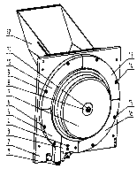
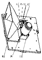
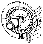
[0020] According to the attached figure 1 , with figure 2 , with image 3 , with Figure 4 The novelty of the present invention is described further.

[0021] The middle hole of the inner concave surface of the ring turntable (7) is provided with a motor connection shaft (24), and one end surface of the ring turntable (7) is provided with a counterbore, and a turntable spacer (8) is arranged in the counterbore, and the motor connection shaft (24) It is connected with the ring turntable (7) by screws (11), the other end of the motor connection shaft (24) is connected with the geared motor (17) by a flat key, and the geared motor (17) is connected with the panel (2) by screws (34), and the panel (2) is provided with annular retaining rings (3), (5), (10), (13), (16), respectively using screws (4), (6), (9), (14), (15 ) connection, the other side of the panel (2) is provided with a silo (12), the silo (12) is provided with a silo connecting plate (19) integrated with the sil...


PUM


Abstract

The invention relates to the technical field of novel convexly-welded nut automatic sorting structures, in particular to a rotating disc type convexly-welded nut automatic sorting structure. The structure is characterized in that an inwards-concave annular rotating disc is adopted, rectangular through grooves which are uniformly distributed in the radial direction are formed in the end surface ofthe annular rotating disc, a certain distance is formed between the end surface of the annular rotating disc and a face board, convex convexly-welded nuts can be accommodated correspondingly, an annular retainer ring is arranged on the outer ring of the annular rotating disc correspondingly, and an annular groove, a straight groove and an arc-shaped groove are formed in the inner surface of one side of the annular retainer ring; and the convex convexly-welded nuts can slide into the straight groove through the annular groove under the driving of the annular rotating disc and by means of the gravity of the nuts, the convexly-welded nuts which are regularly arranged are output through the straight groove, the size of the radial through grooves of the end surface of the annular rotating discand the distance between the end surface of the annular rotating disc and the face board are changed, so that the structure can be used for conveying and sorting different convex convexly-welded nuts.The automatic connection of fasteners has become a technical trend of automobile and household appliance application at present, the structure, an automatic feeding mechanism, a convexly-welded nut automatic conveying mechanism, a convex welding machine and a welding gun are effectively matched, so that the convexly-welded nuts can be automatically welded.

Description

technical field [0001] The invention relates to the technical field of a new type of automatic sorting structure for projection welding nuts. Specifically, it is a concave annular turntable. The inner surface of one side of the annular retaining ring is provided with annular grooves and straight grooves, and the radially evenly distributed rectangular through grooves on the end surface of the turntable allow the hexagonal bosses of the projection welding nuts to pass through. There is a certain distance between them, so that the flange plate of the projection welding nut can pass through, and the outlet of the silo is connected with the panel. The projection welding nut enters the inner concave cavity of the ring turntable from the outlet of the hopper, and the ring turntable is driven by the gear motor to rotate. , drive the projection welding nut inside the turntable to turn over together. When the hexagonal boss with projection welding nut enters the straight groove on the ...

Claims


Application Information

Patent Timeline
Patent Type & Authority Applications(China)
IPC IPC(8): B07B13/00B07B13/16B07B13/14
CPCB07B13/003B07B13/14B07B13/16
Inventor 不公告发明人
Owner 上海兰盈智能科技有限公司
Why Eureka
Try Eureka