AI technical title is built by Patsnap AI team. It summarizes the technical point description of the patent document.
A metal stamping and mold technology, applied in the field of molds, can solve the problems of processing stability or accuracy, increase the labor intensity of workers, warping or moving, etc., to avoid manual removal, avoid movement and warping, and reduce removal. effect of time
Active Publication Date: 2021-02-12
上海东景工艺有限公司
View PDF6 Cites 1 Cited by
Summary
Abstract
Description
Claims
Application Information
AI Technical Summary
This helps you quickly interpret patents by identifying the three key elements:
Problems solved by technology
Method used
Benefits of technology
Problems solved by technology
[0003] When flushing out the remaining material of the metal workpiece, it may be necessary to use a stamping die for processing; some stamping dies carry the workpiece through the cavity, and there may be a gap between the workpiece and the cavity. When processing one side of the workpiece, and The workpiece may be irregular. When one side is under pressure, it may warp or move, which may affect the stability or accuracy of processing; after processing, manual cleaning and collection of residual materials and workpiece cleaning may be required. deducted, which may increase the labor intensity of the staff
Method used
Image
Click on the blue label to locate the original text in one second.
Reading with bidirectional positioning of images and text.
Examples
Embodiment Construction
[0024] In order to make the purpose, features and advantages of the present invention more obvious and understandable, the technical solutions in the embodiments of the present invention will be clearly and completely described below with reference to the accompanying drawings in the embodiments of the present invention. Obviously, the following The described embodiments are only some, but not all, embodiments of the present invention. Based on the embodiments of the present invention, all other embodiments obtained by those of ordinary skill in the art without creative efforts shall fall within the protection scope of the present invention.
[0025] The technical solutions of the present invention are further described below with reference to the accompanying drawings and through specific embodiments.
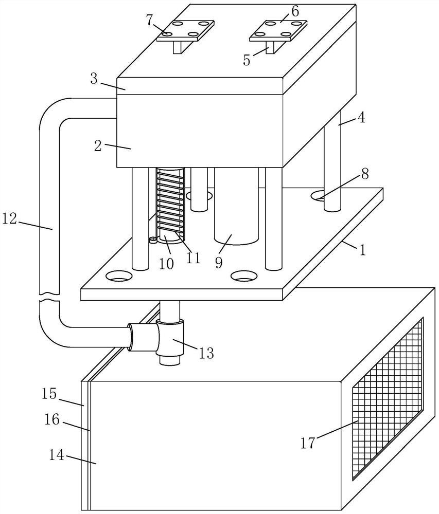
[0026] see Figure 1-6 As shown, a metal stamping die includes a lower die 2, an upper die 3, a bottom plate 1, a cleaning guide material collection structure, a waste discha...
PUM
Abstract
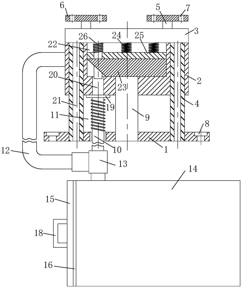
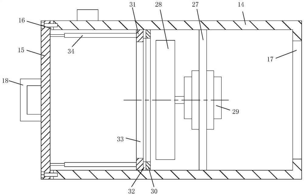
The invention belongs to the field of mold technology, specifically a metal stamping die, including a bottom plate, a lower die, an upper die, a guide sleeve, a connecting strip, a mounting plate, a first mounting hole, a second mounting hole, a fixing sleeve, an electromagnet , guide ring, push block, movable iron rod, first spring, material guide pipe, second spring, connecting pipe, tee pipe, dust collection box, side plate, first rubber ring, first filter screen, handle, ring , discharge hole, guide rod, stamping cavity, metal block, third spring, pressure plate, punch, mounting frame, centrifugal impeller, motor, retaining ring, frame, second rubber ring, second filter screen and gas spring. The invention has a reasonable structure and is suitable for stamping on one side of the metal block to remove excess material. During stamping, before the punch rod contacts the metal block, the pressing plate and the setting of several third springs can be used to compress and limit the metal block in advance. Improve the stability of the metal block when stamping, avoid movement and warping, and improve the accuracy of stamping.
Description
technical field [0001] The invention belongs to the technical field of molds, in particular to a metal stamping mold. Background technique [0002] Stamping is a pressure processing method that uses a die installed on a press to apply pressure to the material at room temperature to cause separation or plastic deformation to obtain the required parts; during processing, part of the remaining material can be punched out, or change its shape. [0003] When flushing the residual material of the metal workpiece, it may be necessary to use a stamping die for processing; some stamping dies carry the workpiece through the groove cavity, and there may be a gap between the workpiece and the groove cavity. The workpiece may also be irregular. When one side is pressed, it may warp or move, which may affect the stability or accuracy of processing; after processing, manual cleaning and collection of residual materials and workpiece cleaning may be required. deducted, which may increase ...
Claims
Application Information
Patent Timeline
Application Date:The date an application was filed.
Publication Date:The date a patent or application was officially published.
First Publication Date:The earliest publication date of a patent with the same application number.
Issue Date:Publication date of the patent grant document.
PCT Entry Date:The Entry date of PCT National Phase.
Estimated Expiry Date:The statutory expiry date of a patent right according to the Patent Law, and it is the longest term of protection that the patent right can achieve without the termination of the patent right due to other reasons(Term extension factor has been taken into account ).
Invalid Date:Actual expiry date is based on effective date or publication date of legal transaction data of invalid patent.

