Sealing structure for horizontal plating tank

A technology of sealing structure and plating tank, applied in sealing devices, electrolysis components, electrolysis process, etc., can solve the problem of less plating tank and achieve the effect of simple structure and continuous plating

Pending Publication Date: 2019-10-22
YANTAI NEWSTAR AERO HYDRAULICS
View PDF4 Cites 0 Cited by
  • Summary
  • Abstract
  • Description
  • Claims
  • Application Information

AI Technical Summary

Problems solved by technology

[0003] The invention aims at the problem that there are few plating tanks used for electroplatin

Method used


Image

  • Sealing structure for horizontal plating tank
  • Sealing structure for horizontal plating tank
  • Sealing structure for horizontal plating tank

Examples


Example Embodiment

[0016] The principles and features of the present invention will be described below with reference to the accompanying drawings. The examples are only used to explain the present invention, but not to limit the scope of the present invention.

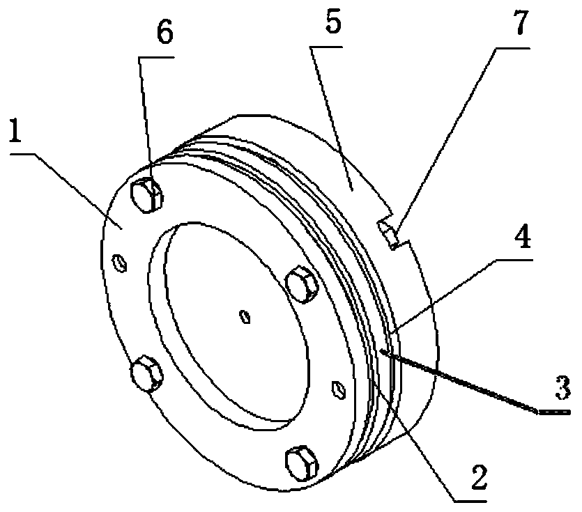
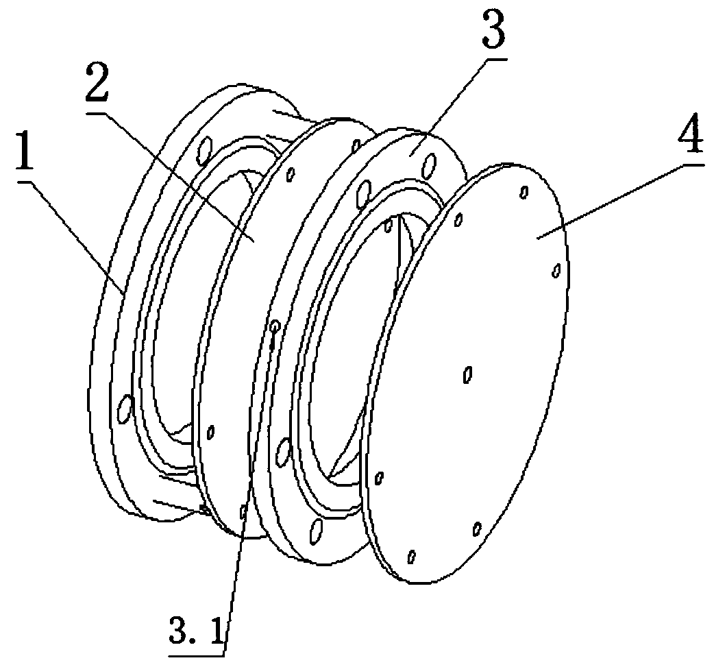
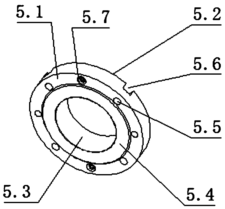
[0017] A sealing structure for horizontal plating tanks (see Figure 1-4 ), including outer sealing flange 1, outer sealing 2, inner sealing flange 3, inner sealing 4 and connecting piece 5; the connecting piece 5 (see image 3 ) comprises an annular connecting ring disk 5.1, the connecting ring disk 5.1 is provided with a fixing hole 5.7 and a bolt connection hole 5.5, the center of the connecting ring disk 5.1 is provided with a ring-shaped convex convex ring disk 5.4, and the outer ring of the connecting ring disk 5.1 is provided with an outer ring The retaining ring 5.2, the edge of the outer retaining ring 5.2 is provided with a bolt installation groove 5.6 which is matched with the bolt connection hole 5.5, the center of the conve...


PUM


Abstract

The invention relates to a sealing structure for a horizontal plating tank. The sealing structure comprises an outer sealing flange, an outer seal, an inner sealing flange, an inner seal and a connecting piece, wherein the connecting piece comprises an annular connecting ring disc; a fixing hole and a bolt connecting hole are formed in the connecting ring disc; an annular convex ring disc is arranged at the center of the connecting ring disc; an outer buckling ring is arranged on the outer ring of the connecting ring disc; a bolt mounting groove matched with the bolt connecting hole is formedin the edge of the outer buckling ring; an inner sealing ring is arranged at the center of the convex ring disc; and a through hole perpendicular to the axis of the inner sealing flange is formed in the side edge of the inner sealing flange. According to the sealing structure, continuous electroplating of long rod parts is achieved through a simple structure, and leakage of electroplating solutionis avoided.

Description

technical field [0001] The invention relates to a sealing structure for a horizontal plating tank, belonging to the technical field of electroplating equipment. Background technique [0002] Most of the existing electroplating tanks are to immerse the material to be electroplated into the electroplating tank from the top of the electroplating tank. This electroplating method is convenient for small or not long plating parts, but for long rods, because it is more than 20m For long rods, this method of electroplating is inconvenient, and because the rods are too long during electroplating, the rods are suspended at both ends, and the upper and lower plating of the rods is not uniform enough. If the vertical plating is performed, the electroplating tank needs to be made The sufficient depth of the horizontal type also needs to be made with sufficient length. If the electroplating tank is too long, the amount of electroplating solution used is also a lot, and the electroplating ...

Claims


Application Information

Patent Timeline
IPC IPC(8): C25D17/00
CPCC25D17/004
Inventor 杨小琛高振华李建伟
Owner YANTAI NEWSTAR AERO HYDRAULICS
Why Eureka
Try Eureka