
Air pressure type glass cleaning device

A cleaning device and air pressure technology, which is applied in building maintenance, construction, building construction, etc., can solve the problems of high work intensity, long time consumption, and slow efficiency, and achieve high work efficiency, simple operation, and high degree of integration Effect

Active Publication Date: 2019-10-22
ZHUJI JIEQIU ENVIRONMENTAL PROTECTION TECH
View PDF5 Cites 2 Cited by
  • Summary
  • Abstract
  • Description
  • Claims
  • Application Information

AI Technical Summary

Problems solved by technology

[0002] With the development of the economy, many high-rise buildings that can accommodate many people to work have been built in the city. The buildings are built higher and higher to accommodate more people. At the same time, for the overall beauty of the city and the reason of light transmission, many The outer walls of the city are made of glass. While glass brings beauty, it also brings cleaning problems. The current way of manually cleaning the outer walls of buildings is slow and extremely dangerous. At the same time, it is also affected by weather and manpower deployment factors. Due to the influence of the problem, it is necessary to install a suspension vehicle during manual cleaning. This method is extremely intensive, takes a long time, and requires a large number of personnel. At the same time, the use of cleaning agents is also a wasteful way of smearing. , so it is necessary to design a pneumatic glass cleaning device that can clean the outer glass surface of the building by itself to solve the above problems

Method used


Image

  • Air pressure type glass cleaning device
  • Air pressure type glass cleaning device
  • Air pressure type glass cleaning device

Examples


Embodiment Construction

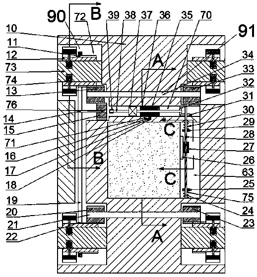
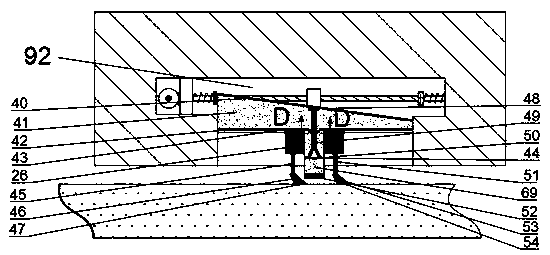
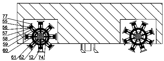
[0022] Combine below Figure 1-5 The present invention is described in detail, and for convenience of description, the orientations mentioned below are now stipulated as follows: figure 1 The up, down, left, right, front and back directions of the projection relationship itself are the same.

[0023] combined with Figure 1-5 The pneumatic glass cleaning device includes a body 10, the body 10 includes a cleaning chamber 63, and the cleaning chamber 63 is provided with a cleaning mechanism 92 for cleaning the glass by spraying the cleaning agent solution and sliding the blade, The cleaning chamber 63 is extended and rotated up and down to be provided with a first rotating shaft 24, and the first rotating shaft 24 is fixedly provided with a spiral groove 28, and the first rotating shaft 24 slides up and down to be provided with a first slider 27, and the first rotating shaft 24 An internal thread 65 engaged with the spiral groove 28 is fixed inside the slider 27;

[0024] The...


PUM


Abstract

The invention discloses an air pressure type glass cleaning device. The device comprises a body, wherein the body comprises a cleaning cavity; a cleaning mechanism for glidingly cleaning the glass through spraying cleaning agent solution and using a doctor blade is arranged in the cleaning cavity; a first rotation shaft is rotatably arranged in the cleaning cavity in an up-down extension manner; aspiral groove is fixedly formed in the first rotation shaft; and a first sliding block is arranged on the first rotation shaft in an up-down sliding manner. At first, the device is vertically fixed on the outer surface of a building, preliminarily cleans the glass and then finally cleans the glass through spraying out the vaporous cleaning agent; after the cleaning of one piece of glass is completed, the device automatically moves to the next glass, the cleaning mechanism is reset and cleaning is carried out again when the device reaches the next glass; the process is high in working efficiency and has a relatively high integration degree; meanwhile, the device is high in kinetic energy utilization rate; the using of the cleaning agent is capable of efficiently utilizing and saving the energy; and meanwhile, the operation is simple and the process is safe and rapid.

Description

technical field [0001] The invention relates to the field of high-altitude glass cleaning, in particular to a pneumatic glass cleaning device. Background technique [0002] With the development of the economy, many high-rise buildings that can accommodate many people to work have been built in the city. The buildings are built higher and higher to accommodate more people. At the same time, for the overall beauty of the city and the reason of light transmission, many The outer walls of the city are made of glass. While glass brings beauty, it also brings cleaning problems. The current way of manually cleaning the outer walls of buildings is slow and extremely dangerous. At the same time, it is also affected by weather and manpower deployment factors. Due to the influence of the problem, it is necessary to install a suspension vehicle during manual cleaning. This method is extremely intensive, takes a long time, and requires a large number of personnel. At the same time, the u...

Claims


Application Information

Patent Timeline
Patent Type & Authority Applications(China)
IPC IPC(8): E04G23/00
CPCE04G23/002
Inventor 周正
Owner ZHUJI JIEQIU ENVIRONMENTAL PROTECTION TECH
Learn More