
Precise adjustment lens frame for large-aperture optical element

A technology for optical components and precise adjustment, which is applied in the direction of optical components, optics, instruments, etc., can solve the problems of increasing the load bearing of optical components, large installation space requirements, and easy interference of optical paths, so as to meet the installation and adjustment requirements and save space , the effect of not interfering with the optical path

Pending Publication Date: 2019-10-22
INST OF MACHINERY MFG TECH CHINA ACAD OF ENG PHYSICS
View PDF0 Cites 2 Cited by
  • Summary
  • Abstract
  • Description
  • Claims
  • Application Information

AI Technical Summary

Problems solved by technology

[0003] 1. The adjustment mechanism of the existing adjustment frame is installed on both sides of the optical element, which requires a large installation space and the structure is not compact;
[0004] 2. Since there are adjustment mechanisms on both sides of the mirror surface, the optical path is easily disturbed, and if the left and right sides need optical path transmission, it cannot meet the requirement that the left and right sides of the mirror lens can be arbitrarily close;
[0005] 3. Since there are adjustment mounts on both sides of the optical element, it will not be able to meet the cleanliness requirements of the precision grating due to the obstruction of the parts of the adjustment mounts on both sides;
[0006] 4. The adjustment mechanism of the existing adjustment frame is installed on both sides of the optical element, which increases the load bearing of the optical element and easily causes damage to the mirror lens

Method used


Image

  • Precise adjustment lens frame for large-aperture optical element
  • Precise adjustment lens frame for large-aperture optical element
  • Precise adjustment lens frame for large-aperture optical element

Examples


Embodiment 1

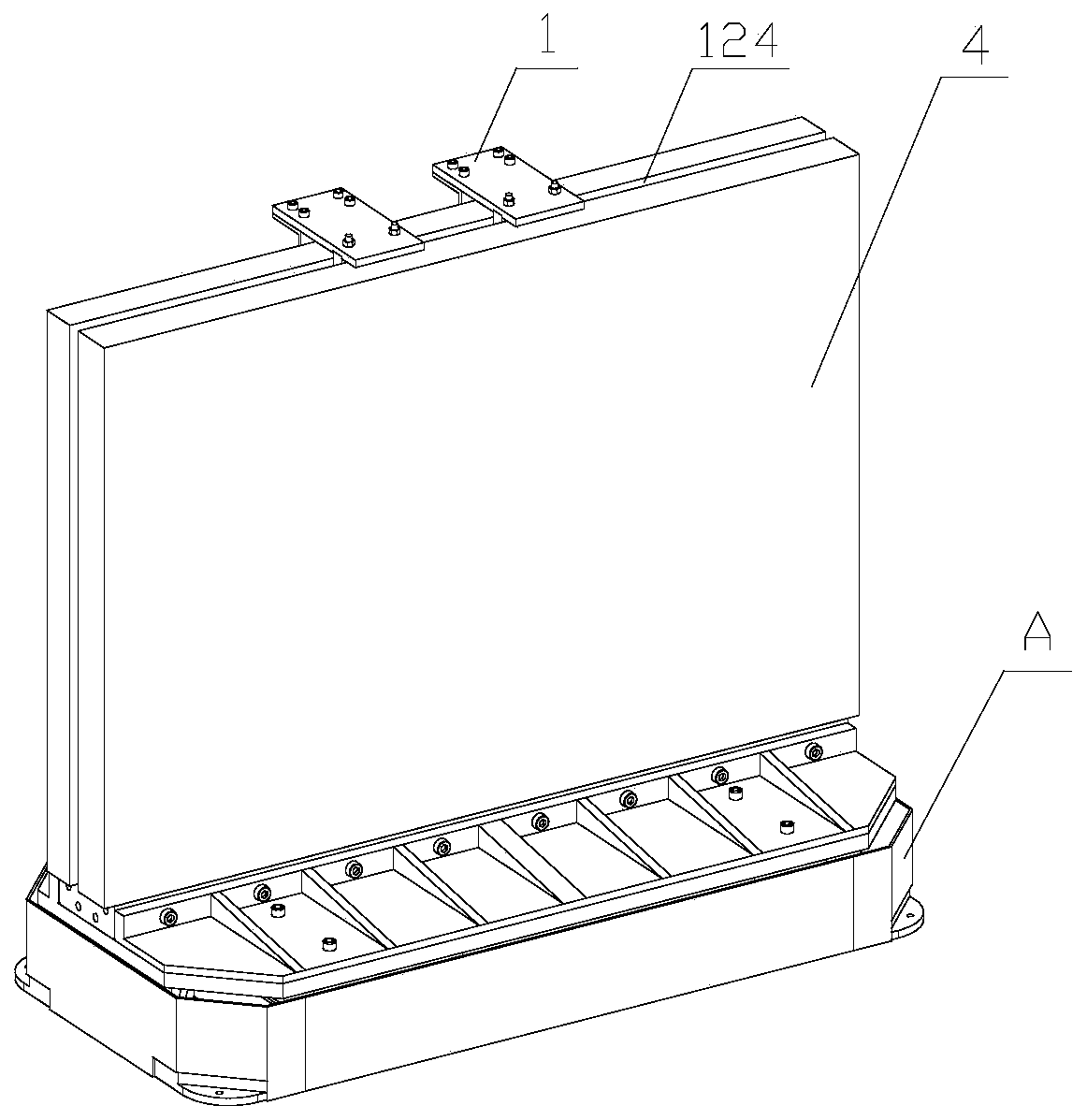
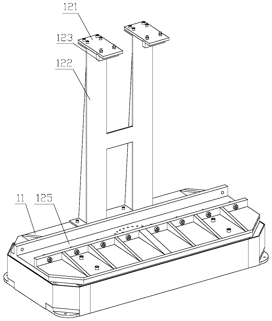
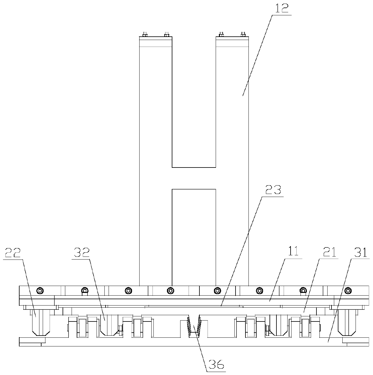
[0058] This embodiment provides a precision adjustment frame for large-diameter optical elements, including a mounting assembly 1, an adjustment mechanism and a platform, and the adjustment mechanism is fixed on the platform. The adjustment mechanism includes a deflection assembly 2 and a pitch assembly 3, the installation assembly 1 includes a first layer 11 and a positioning member 12; the deflection assembly 2 includes a second layer 21 and a deflection drive member 22, and the pitch assembly 3 includes The third layer plate 31 and the tilting driving member 32;

[0059] The first laminate 11, the second laminate 21 and the third laminate 31 are arranged sequentially from top to bottom, and the first laminate 11, the second laminate 21 and the third laminate 31 are rectangular parallelepiped or similar The board structure, and the three boards are arranged parallel to each other;

[0060] The positioning part 12 is arranged on the first laminate 11 and is located above the...

Embodiment 2

[0064] Further improvement on the basis of Embodiment 1, the positioning member 12 includes a mounting base plate 121 and a ribbed steel plate 122, the mounting base plate 121 adopts a steel plate structure; one end of the mounting base plate 121 is connected to the first layer plate 11 through the ribbed steel plate 122, The axial ends of the ribbed steel plate 122 are respectively detachably connected to the mounting base plate 121 and the first layer plate 11 through bolts; the other end of the mounting base plate 121 is used to clamp the optical element 4, and the upper and lower ends of the optical element 4 are clamped on the mounting base plate 121 between the lower surface and the upper surface of the first laminate 11 . The positioning part 12 also includes a polytetrafluoroethylene insert 123, and the polytetrafluoroethylene insert 123 is fixed on the other end of the mounting substrate 121 by bolts; the top of the optical element 4 is provided with a positioning groo...

Embodiment 3

[0066] Further improvement on the basis of Embodiment 2, both the yaw driving member 22 and the pitching driving member 32 adopt a linear motion drive, and the linear motion drive includes a servo motor assembly 51, a coupling 52, a nut 53, and a screw rod 54 , nut seat 55, linear guide rail 56 and base 57; the servo motor assembly 51 includes a brushless servo motor and a zero-backlash reducer, and the nut 53 and the screw mandrel 54 respectively adopt an anti-backlash screw rod and an anti-backlash nut; the servo motor assembly 51 is After the reducer decelerates, the screw 54 is driven to rotate through the coupling 52, and the nut 53 drives the nut seat 55 to move linearly on the linear guide rail 56 under the drive of the screw 54; On the lower plate surface of the lower plate, the pitch drive assembly 32 is fixed on the upper plate of the third layer plate 31 through the base 57;

[0067] The free end of the nut 53 is hingedly connected with the first layer 11 or the sec...


PUM


Abstract

The present invention discloses a precise adjustment lens frame for a large-aperture optical element. The precise adjustment lens frame comprises a mounting assembly and an adjusting mechanism; the adjusting mechanism comprises a deflection assembly and a pitching assembly; the mounting assembly is used for fixing the optical element; the deflection assembly comprises a second layer plate and a deflection driving component; the pitching assembly comprises a third layer plate and a pitching driving component; the first layer plate, the second layer plate and the third layer plate are sequentially arranged from top to bottom; the first layer plate and the second layer plate are rotatably connected with each other; the second layer plate is provided with the deflection driving component whichdrives the first layer plate to perform deflection movement; the lower plate surface of the second layer plate is provided with arc-shaped guide rails; the upper plate surface of the third layer plate is provided with cushion blocks in pairs; and the arc-shaped guide rails slide on the cushion blocks, so that the pitching driving component drives the second layer plate to perform pitching motion.The adjusting mechanism of the lens frame provided by the present invention is arranged below the optical lens, and therefore, space can be saved, a light path will not be interfered, and the cleanliness of the optical element will not be influenced; and load bearing is concentrated below the optical element, the optical element does not bear load, and therefore, the optical element can be effectively protected.

Description

technical field [0001] The invention relates to the technical field of optical devices, in particular to a mirror frame for precision adjustment of large-diameter optical elements. Background technique [0002] Large-diameter optical components are an important part of high-power solid-state laser devices. For example, the ignition device (NIF) contains more than 800 large-diameter mirrors. These large-diameter mirrors can be used to guide the beam. The function is to guide the beam to etch the grating through the precise control of the attitude of the large-aperture mirror. Generally, in the prior art, the adjustment mirror holders for the large-aperture reflectors are arranged in half on both sides of the optical element, which has the following disadvantages: [0003] 1. The adjustment mechanism of the existing adjustment frame is installed on both sides of the optical element, which requires a large installation space and the structure is not compact; [0004] 2. Since...

Claims


Application Information

Patent Timeline
Patent Type & Authority Applications(China)
IPC IPC(8): G02B7/182
CPCG02B7/1821
Inventor 李月李斌徐猛连克难付兴王骁朱建平
Owner INST OF MACHINERY MFG TECH CHINA ACAD OF ENG PHYSICS
Learn More