Pressurized water reactor containment vessel two-side condensation and evaporation coupling calculation method

A technology of pressurized water reactors and calculation methods, applied in calculation, computer-aided design, design optimization/simulation, etc., can solve problems such as lack of

Active Publication Date: 2019-10-22
XI AN JIAOTONG UNIV
View PDF13 Cites 10 Cited by
  • Summary
  • Abstract
  • Description
  • Claims
  • Application Information

AI Technical Summary

Problems solved by technology

However, calculations focus more on the calculation of a single phenomenon on one side. Although it can provide some guidance for the design of the containment and capacity assessment, this single-phenomenon calculation lacks g

Method used


Image

  • Pressurized water reactor containment vessel two-side condensation and evaporation coupling calculation method
  • Pressurized water reactor containment vessel two-side condensation and evaporation coupling calculation method
  • Pressurized water reactor containment vessel two-side condensation and evaporation coupling calculation method

Examples


Embodiment Construction

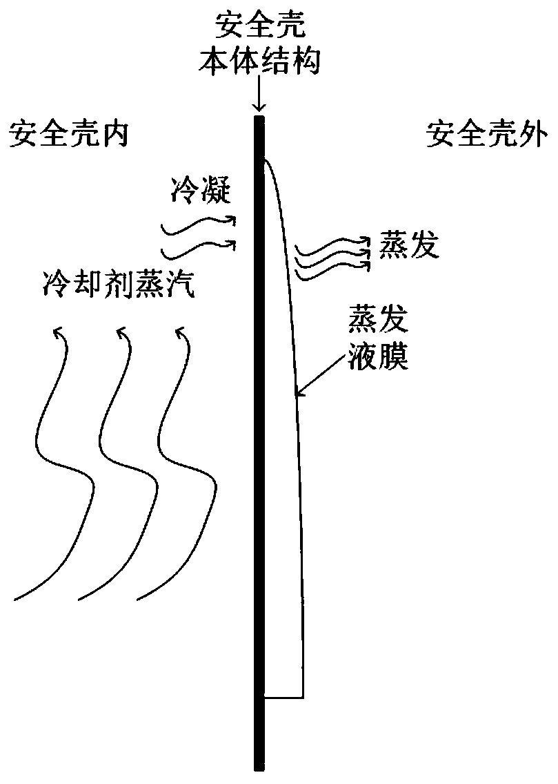
[0094] Combine the following Figure 4 As shown in the flow chart, the present invention is further described in detail by taking the coupling calculation process of condensation and evaporation inside and outside a typical PWR containment vessel as an example. In addition, the typical PWR containment vessel structure is as follows: figure 1 shown. Under accident conditions, the key thermal hydraulic phenomena inside and outside the PWR containment vessel are: figure 2 shown.

[0095] The present invention provides a method for calculating the coupling of condensation and evaporation on both sides of a pressurized water reactor containment vessel, comprising the following steps:

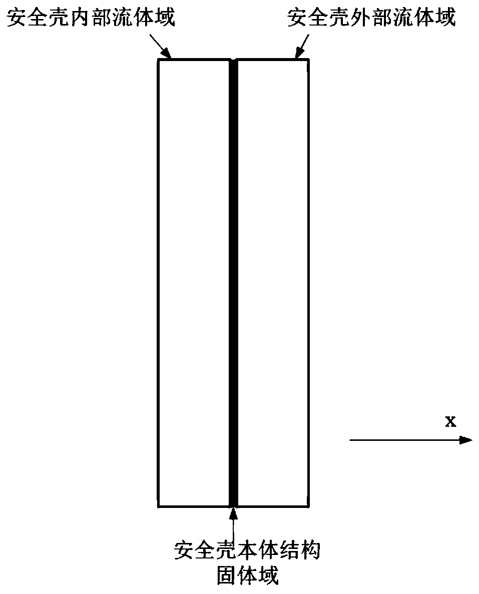
[0096] Step 1: Establish a simplified model of the PWR containment computational domain, including the internal fluid domain of the PWR containment, the external fluid domain of the PWR containment, and the solid domain model of the PWR containment body structure, a three-part computational domain...


PUM


Abstract

The invention discloses a pressurized water reactor containment vessel two-side condensation and evaporation coupling calculation method. The method comprises the following steps: establishing a pressurized water reactor containment vessel computational domain simplified geometric model; performing grid generation on each part in the pressurized water reactor containment vessel computational domain model to obtain a grid model of each part; setting an interface of each part in a calculation domain of the pressurized water reactor containment as a grid interface to realize splicing of grids ofeach part; performing steam condensation calculation in the range of the fluid domain grid model in the containment vessel; calculating the temperature distribution in the solid domain of the containment body structure through the heat conduction relational expression; and calculating a flow field and a temperature field of a liquid film in an external fluid domain of the containment vessel by adopting a liquid film model.

Description

technical field [0001] The invention belongs to the technical field of thermal hydraulic calculation of nuclear reactors, and particularly relates to a method for coupling condensation and evaporation on both sides of a pressurized water reactor containment vessel. Background technique [0002] The containment is the last barrier to prevent the release of radioactive substances in the pressurized water reactor nuclear power plant, so ensuring the integrity of the containment is crucial to ensure the safety of the nuclear power plant. Under this premise, at present, PWR nuclear power plants, such as AP1000, are equipped with a containment cooling system for containment cooling under accident conditions. In the event of a rupture in the primary circuit of the reactor, a large amount of coolant flashes into superheated steam, but with the discharge of the coolant steam, the pressure and temperature in the containment rise sharply, which affects the integrity of the containment....

Claims


Application Information

Patent Timeline
IPC IPC(8): G06F17/50
CPCG06F30/23G06F2119/06
Inventor 王明军李俊房迪田文喜秋穗正苏光辉
Owner XI AN JIAOTONG UNIV
Why Eureka
Try Eureka