High-voltage circuit breaker with self-locking function
A high-voltage circuit breaker and functional technology, applied in circuits, parts of protection switches, electrical components, etc., can solve problems such as circuit breakers and switch paths, and achieve the effects of high reliability, sensitive action response, and strong practicability
- Summary
- Abstract
- Description
- Claims
- Application Information
AI Technical Summary
Problems solved by technology
Method used
Image

Examples
Embodiment Construction
[0042]The technical solutions in the present invention will be clearly and completely described below in conjunction with the accompanying drawings in the embodiments of the present invention. Obviously, the described embodiments are only some of the embodiments of the present invention, not all of them. Based on the embodiments of the present invention, all other embodiments obtained by persons of ordinary skill in the art without creative efforts fall within the protection scope of the present invention.
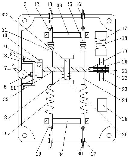
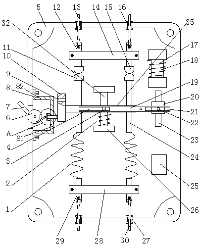
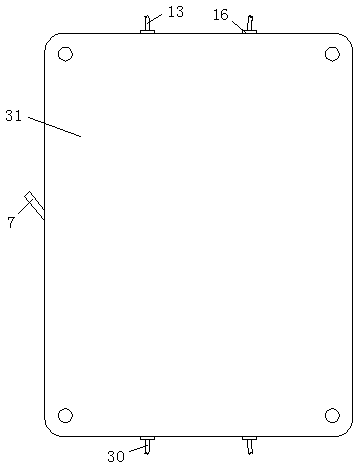
[0043] Such as figure 1 , figure 2 and image 3 As shown, the high-voltage circuit breaker with self-locking function provided by the present invention includes: a lower case 5 and an upper case 31 matching the lower case 5, the lower case 5 is connected with the upper case 31 to form a complete The housing, the four corners of the lower housing 5 and the upper housing 31 are threaded.
[0044] The upper and lower ends of the lower housing 5 are provided with two symme...
PUM
 Abstract
Description
Claims
Application Information
PatSnap Eureka turns technology decisions into work you can execute. Powered by our Innovation Knowledge Graph, it runs expert workflows across engineering, life sciences, materials and intellectual property. Get your review-ready output in minutes.


