
Drive-driven-combined prosthesis knee and ankle joint hydraulic loop with energy recycling function

A technology of energy recovery and hydraulic circuit, applied in prosthetics, medical science, artificial legs, etc., can solve the problems of uncontrollable energy absorption and release of the foot, short battery life, high energy consumption of lower limb prostheses, and achieve simple structure and extended Long-lasting, easy-to-achieve effects

Active Publication Date: 2019-10-25
JILIN UNIV
View PDF9 Cites 3 Cited by
  • Summary
  • Abstract
  • Description
  • Claims
  • Application Information

AI Technical Summary

Problems solved by technology

[0004] The purpose of the present invention is to solve the problems of high energy consumption, short battery life, and uncontrollable energy absorption and release of the foot in the existing lower limb prostheses in the background technology, and to provide an active-passive combined prosthetic knee-ankle hydraulic joint with energy recovery function. loop

Method used


Image

  • Drive-driven-combined prosthesis knee and ankle joint hydraulic loop with energy recycling function
  • Drive-driven-combined prosthesis knee and ankle joint hydraulic loop with energy recycling function
  • Drive-driven-combined prosthesis knee and ankle joint hydraulic loop with energy recycling function

Examples


Embodiment Construction

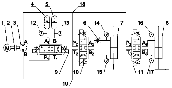
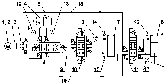
[0031] see Figure 1 to Figure 6 As shown, an active-passive combined prosthetic knee-ankle joint hydraulic circuit with energy recovery function includes a motor 1, a coupling 2, a hydraulic pump 3, a first accumulator 4, a second accumulator 5, and an adjustable flow valve 6. Knee joint hydraulic cylinder 7, ankle joint hydraulic cylinder 8, first three-position four-way proportional valve 9, second three-position four-way proportional valve 10, third three-position four-way proportional valve 11, first pressure sensor 12, The second pressure sensor 13, the third pressure sensor 14, the fourth pressure sensor 15, the fifth pressure sensor 16, the sixth pressure sensor 17, the first pipeline 18 and the second pipeline 19, the motor 1 is connected with the shaft coupling 2 The hydraulic pump 3 is connected, and the first pipeline 18 is connected to the A port of the hydraulic pump 3, the P1 port of the first three-position four-way proportional valve 9, the P2 port of the seco...


PUM


Abstract

The invention discloses a drive-driven-combined prosthesis knee and ankle joint hydraulic loop with an energy recycling function and aims to solve the problems that a drive hydraulic prosthesis systemis high in energy consumption, short in endurance time and the like. The hydraulic loop comprises a motor, a coupler, a hydraulic pump, a first energy storage device, a second energy storage device,an adjustable throttling valve, a knee joint hydraulic cylinder, an ankle joint hydraulic cylinder, a first three-position four-way proportional valve, a second three-position four-way proportional valve, a third three-position four-way proportional valve, a first pressure sensor, a second pressure sensor, a third pressure sensor, a fourth pressure sensor, a fifth pressure sensor, a sixth pressuresensor, a first pipeline and a second pipeline . The hydraulic loop has the advantages that the energy storage devices are controlled through the three-position four-way proportional valves to absorband release energy generated during human body walking, system energy consumption can be effectively lowered by further using the drive-driven-combined drive mode, the performance of lower-limb prosthesis is increased evidently, and structure simpleness and lightweight are achieved conveniently at the same time.

Description

technical field [0001] The invention relates to the technical field of hydraulic control, in particular to an active-passive combined prosthetic knee-ankle joint hydraulic circuit with energy recovery function. Background technique [0002] According to the second national sample survey of disabled people, it is estimated that the number of amputee patients in China is 2.26 million, of which 70% are lower limb amputee. Prosthetics are one of the important means to solve the mobility impairment of many patients. It uses bionic mechanical structures and drive systems to compensate the functions of the missing limbs of disabled people and reproduce the biomechanical characteristics of their missing joints. [0003] Existing studies have shown that during human walking, there is significant energy transmission between the knee and ankle joints, thereby reducing walking energy consumption. Currently, the vast majority of knee prostheses are non-powered, and users need to consume...

Claims


Application Information

Patent Timeline
Patent Type & Authority Applications(China)
IPC IPC(8): A61F2/64A61F2/66A61F2/70A61F2/74
CPCA61F2/64A61F2/6607A61F2/68A61F2002/701A61F2/74A61F2/748
Inventor 刘春宝李振男任雷王同建
Owner JILIN UNIV
Learn More