
Biomass particle cooler

A technology of biomass particles and coolers, which is applied in household refrigeration devices, chemical instruments and methods, lighting and heating equipment, etc. It can solve the problems of insufficient cooling and heat dissipation, residual heat, and poor cooling effect of counter-flow coolers.

Inactive Publication Date: 2019-10-25
ANHUI DING BEAM BIO ENERGY TECH DEV CO LTD
View PDF5 Cites 0 Cited by
  • Summary
  • Abstract
  • Description
  • Claims
  • Application Information

AI Technical Summary

Problems solved by technology

In the prior art, a counter-flow cooler is generally used to achieve the purpose of cooling, but the cooling effect of the counter-flow cooler is not good, and some heat is often left, which cannot meet its cooling and heat dissipation standards

Method used


Image

  • Biomass particle cooler
  • Biomass particle cooler
  • Biomass particle cooler

Examples


Embodiment Construction

[0025] The present invention will be described in further detail below in conjunction with the accompanying drawings.

[0026] This specific embodiment is only an explanation of the present invention, and it is not a limitation of the present invention. Those skilled in the art can make modifications to this embodiment without creative contribution as required after reading this specification, but as long as they are within the rights of the present invention All claims are protected by patent law.

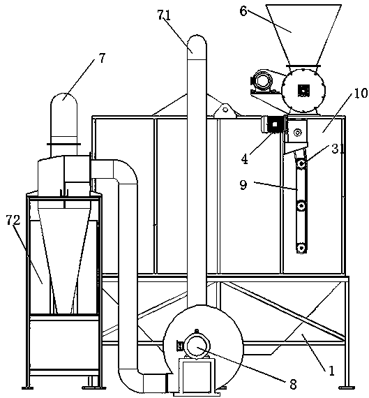
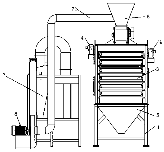
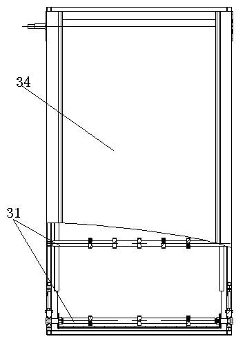
[0027] Such as figure 1 figure 2 Figure 5 The biomass particle cooler shown includes a base 1, a bracket is arranged above the base, and a cooling bin 10 is placed on the bracket. The cooling bin 10 is a place for cooling biomass particles. The cooling bin 10 is provided with a multi-layer transportation network. Belt 3, the biomass particles used for cooling pass through the feed hopper 6 and then evenly scatter on the transport mesh belt 3. An air outlet 2 is provided above...


PUM


Abstract

The invention provides a biomass particle cooler and belongs to the field of coolers. The biomass particle cooler comprises a base and a cooling bin located on the base. The upper portion of the cooling bin is provided with an air outlet. The air outlet is connected with a fan. The biomass particle cooler further comprises a multilayer heat dissipation device. The multilayer heat dissipation device comprises conveying mesh belts and driving motors. The conveying mesh belts are arranged correspondingly in the vertical direction. The two driving motors are arranged and drive the odd layers and the even layers of the conveying mesh belts correspondingly. The cooling bin is arranged in the cooler, the multilayer conveying mesh belts are arranged in the cooling bin and are provided with small holes, biomass particles are conveyed layer by layer by the conveying mesh belts to make full contact with air in the cooling bin, and cooling and heat dissipation purposes are achieved.

Description

technical field [0001] The invention relates to the field of coolers, in particular to a biomass particle cooler. Background technique [0002] In recent years, human social and economic development has become increasingly rapid, but this is at the cost of a large amount of fossil energy consumption and pollution of the environment. Renewable energy, which has the dual attributes of renewability and environmental friendliness, has attracted more and more attention in recent years. my country is a big energy-consuming country, so adjusting the energy structure and using biomass energy is an inevitable choice. After the biomass is compressed and molded, its volume is greatly reduced, which makes it easier to transport, store and use, and solves the key problem of large-scale utilization of biomass. Therefore, this technology and equipment are very suitable for clean energy transformation of biomass power generation and industrial boilers , New rural cooking fuel. Biomass pe...

Claims


Application Information

Patent Timeline
Patent Type & Authority Applications(China)
IPC IPC(8): F25D31/00B08B5/02
CPCB08B5/02F25D31/00
Inventor 朱华梁念喜阮景波王靖东
Owner ANHUI DING BEAM BIO ENERGY TECH DEV CO LTD
Learn More