
Special permanent magnet synchronous motor cooling system structure for bucket elevator

A technology of cooling system and permanent magnet synchronization, applied in the direction of electromechanical devices, electric components, cooling/ventilation devices, etc., can solve the problems of oil leakage of reducer, motor burnout, overheating of motor coils, etc., to ensure safe and reliable operation, Reduced maintenance costs and improved cooling performance

Pending Publication Date: 2020-10-13
南京迪瓦永磁科技有限公司
View PDF0 Cites 0 Cited by
  • Summary
  • Abstract
  • Description
  • Claims
  • Application Information

AI Technical Summary

Problems solved by technology

[0002] At present, the bucket elevator in the domestic cement industry uses an ordinary asynchronous motor with a reducer drive structure. The heat dissipation of the reducer is mainly composed of a cooling fan and a cooling coil. Due to the harsh working environment of the bucket elevator, the reducer is prone to oil leakage and bearing wear. , gear wear, and a series of problems such as high energy consumption, high maintenance rate and maintenance cost, when the ambient temperature reaches 40°C, it is easy to cause damage to the reducer
[0003] In recent years, permanent magnet synchronous direct drive motors have become more and more widely used in bucket elevators in the cement industry. It has the advantages of high overall efficiency, low maintenance, and large overload starting capacity. However, due to high ambient temperature and large loads, permanent If the magnetic synchronous direct drive motor only adopts natural heat dissipation or simple external air cooling without special design, the motor coil will overheat quickly, causing the motor to burn out and causing property loss to the user

Method used


Image

  • Special permanent magnet synchronous motor cooling system structure for bucket elevator
  • Special permanent magnet synchronous motor cooling system structure for bucket elevator
  • Special permanent magnet synchronous motor cooling system structure for bucket elevator

Examples


Embodiment Construction

[0016] The present invention will be described in detail below in conjunction with the accompanying drawings and specific embodiments.

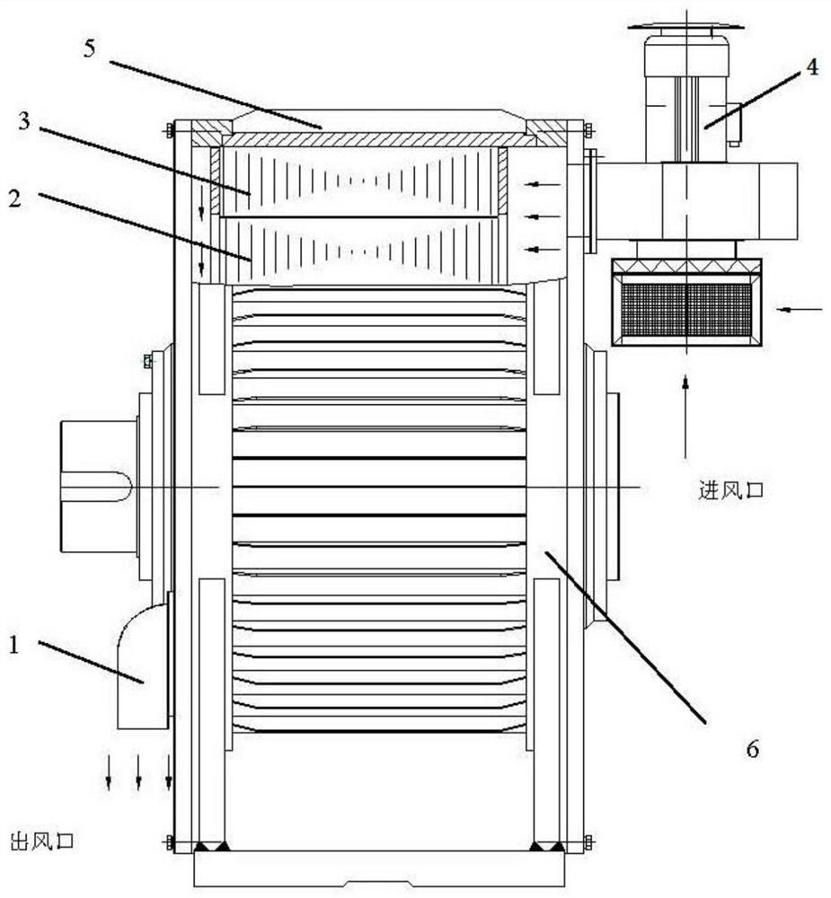
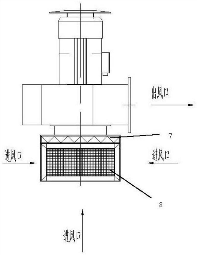
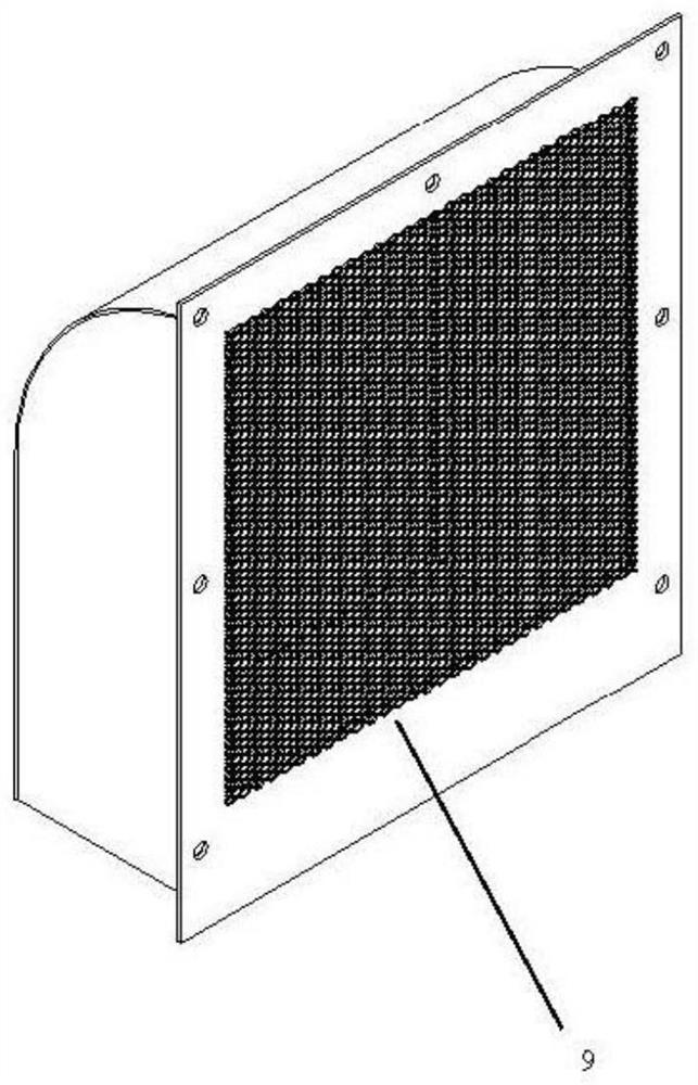
[0017] Such as figure 1 As shown, the present invention provides a cooling system structure for a bucket elevator permanent magnet synchronous direct drive motor in the cement industry, and the cooling system structure includes an external cooling system and an internal cooling system. The external cooling system includes heat dissipation ribs 5 arranged on the outer surface of the motor base 6, and the built-in cooling system includes ventilation holes of the end cover of the shaft extension, ventilation holes of the end cover of the non-shaft extension, cooling fan 4 and outlet The wind guide cover 1, the ventilation hole of the end cover of the shaft extension is used as the air outlet, and the air guide cover 1 of the air outlet is installed at the air outlet, the ventilation hole of the end cover of the non-shaft extension is used as the...


PUM


Abstract

The invention discloses a special permanent magnet synchronous motor cooling system structure for a bucket elevator. The cooling system structure comprises an external cooling system and an internal cooling system; the external cooling system comprises a radiating rib plate arranged on the outer surface of a motor base; the built-in cooling system comprises a shaft extension end cover ventilationhole, a non-shaft-extension end cover ventilation hole, a cooling fan and an air outlet wind scooper; the shaft extension end cover ventilation hole is used as an air outlet; the air outlet wind scooper is installed at the air outlet; the non-shaft-extension end cover ventilation hole serves as an air inlet; the cooling fan is installed at the air inlet; a heat dissipation air channel is formed between the air inlet and the air outlet; and cooling air in the heat dissipation air channel passes through the outer surface of a rotor and the inner surface of a stator. The motor stator and the motor rotor are cooled through combined action of the inner cooling system and the outer cooling system, the temperature of the motor is effectively reduced, and stable and reliable operation of the motoris jointly guaranteed.

Description

technical field [0001] The invention relates to a permanent magnet synchronous direct drive motor cooling system, in particular to a permanent magnet synchronous direct drive motor cooling system structure for bucket elevators in the cement industry. Background technique [0002] At present, the bucket elevator in the domestic cement industry uses an ordinary asynchronous motor with a reducer drive structure. The heat dissipation of the reducer is mainly composed of a cooling fan and a cooling coil. Due to the harsh working environment of the bucket elevator, the reducer is prone to oil leakage and bearing wear. , gear wear, and a series of problems such as high energy consumption, high maintenance rate and maintenance cost, when the ambient temperature reaches 40 ℃, it is easy to cause damage to the reducer. [0003] In recent years, permanent magnet synchronous direct drive motors have become more and more widely used in bucket elevators in the cement industry. It has the ...

Claims


Application Information

Patent Timeline
Patent Type & Authority Applications(China)
IPC IPC(8): H02K5/18H02K5/20H02K5/10H02K9/04
CPCH02K5/10H02K5/18H02K5/20H02K9/04
Inventor 朱见昌
Owner 南京迪瓦永磁科技有限公司
Learn More