
Novel electric shearing machine structure

An electric shear and motor technology, applied in metal processing and other directions, can solve problems such as the weight of the whole machine, affecting the service life of the motor, and the inability of heat to be effectively dissipated.

Pending Publication Date: 2018-07-10
BEIYUAN AUSTRALIA
View PDF8 Cites 0 Cited by
  • Summary
  • Abstract
  • Description
  • Claims
  • Application Information

AI Technical Summary

Problems solved by technology

[0002] At present, the common electric shearing machines on the market are basically composed of key parts such as a shearing head, a reducer (or without a reducer), and a motor. The motor part is relatively large in size and the whole machine is relatively heavy, which will affect the shearing operation. Flexibility and shearing efficiency; at the same time, most of these electric shearing machines use semi-open motors, which work under the condition of dust and wool stubble, foreign matter will be sucked into the motor along with the heat dissipation system of the motor, directly affecting the use of the motor life
Or use a large-volume enclosed motor. In this case, the heat generated by the motor and the shearing moving part cannot be effectively dissipated. The shearing hand will feel uncomfortable when holding such an electric shearing machine under heavy load for a long time. Machine overheating

Method used


Image

  • Novel electric shearing machine structure
  • Novel electric shearing machine structure
  • Novel electric shearing machine structure

Examples


Embodiment Construction

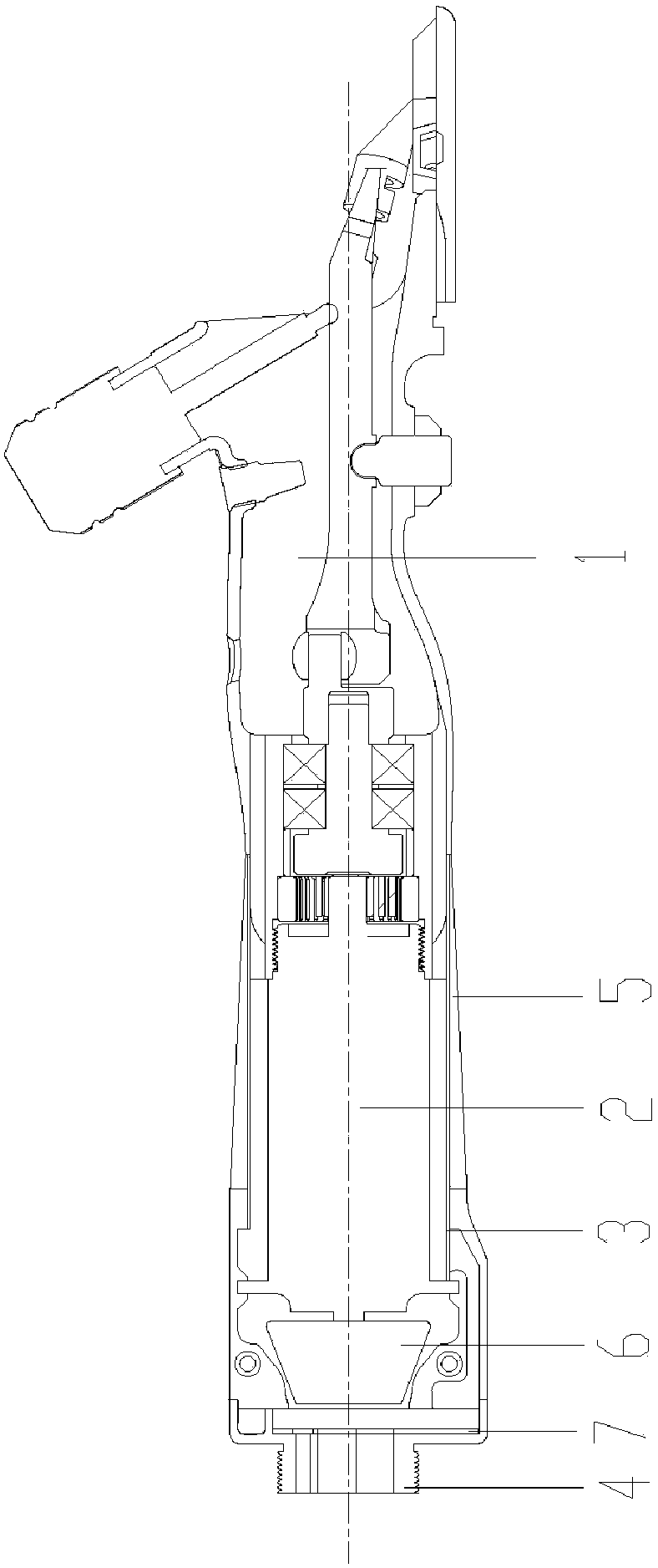
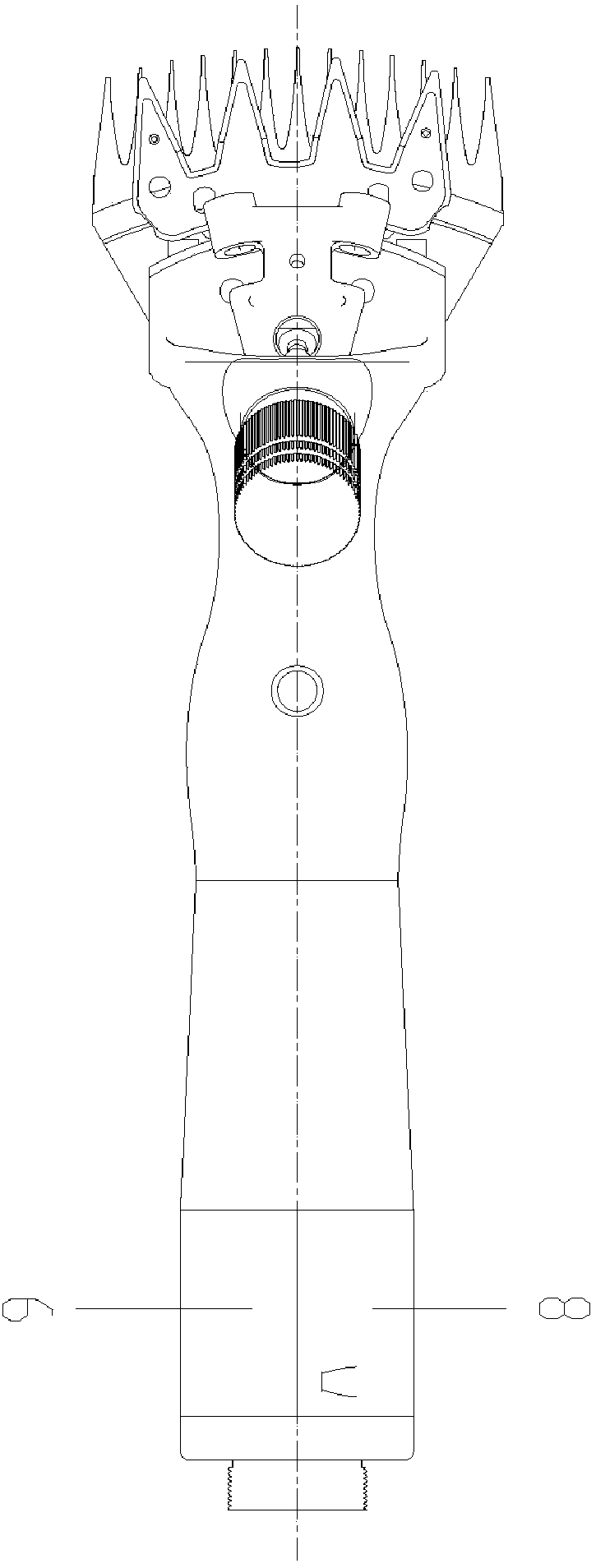
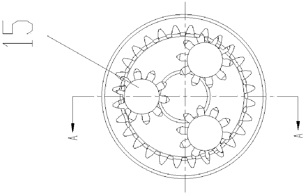
[0040] A new type of electric shearing machine structure, such as Figure 1 to Figure 4 As shown, it includes a motor 2, a cylinder 3, a connection socket 4, a planetary reducer and a fan 6 composed of a planetary carrier 13, a planetary gear 15, and a planetary shaft 16; it also includes a metal machine head body 1, a silicone sleeve 5, and a fan 6. Wiring board 7, right rear end cover 8, left rear end cover 9, ring gear 10, gasket 11, bearing 12, eccentric shaft 14; external thread and metal machine head provided on the circular power output end of motor 2 The internal threads provided in the inner hole of the rear part of the body 1 are assembled together in a threaded manner; the outer circle of the metal machine head body 1 is provided with several upwardly protruding first reinforcing ribs and air holes penetrating from the outside to the inside. The flowing air generated by the rotation of the fan 6 enters from the rear of the whole structure, and flows out from the ins...


PUM


Abstract

The invention belongs to the technical improvement of an electric shearing machine, and particularly relates to a novel electric shearing machine structure. The structure comprises a motor, a cylinder, a wiring socket, a planetary reducer and a fan, wherein the planetary reducer is composed of a planet carrier, planetary gears and a planetary shaft; and the structure further comprises a metal machine head body, a silica gel sleeve, the fan, a wiring board, a right rear end cover, a left rear end cover, a gear ring, a gasket, bearings and an eccentric shaft. According to the structure, the motor is used, the high-efficiency and compact planetary gear reducer is coordinated, the motor is provided with the fan for guiding external air to cool the motor and the whole machine in a mode of flowing from the rear part to a machine head body, so that the requirements for flexible and convenient shearing can be met.

Description

technical field [0001] The invention belongs to the technological improvement of an electric shearing machine, in particular to a novel structure of an electric shearing machine. Background technique [0002] At present, the common electric shearing machines on the market are basically composed of key parts such as a shearing head, a reducer (or without a reducer), and a motor. The motor part is relatively large in size and the whole machine is relatively heavy, which will affect the shearing operation. Flexibility and shearing efficiency; at the same time, most of these electric shearing machines use semi-open motors, which work under the condition of dust and wool stubble, foreign matter will be sucked into the motor along with the heat dissipation system of the motor, directly affecting the use of the motor life. Or use a large-volume enclosed motor. In this case, the heat generated by the motor and the shearing moving part cannot be effectively dissipated. The shearing ...

Claims


Application Information

Patent Timeline
Patent Type & Authority Applications(China)
IPC IPC(8): B26B19/24B26B19/28
CPCB26B19/24B26B19/28
Inventor 张天桥张旭金涛
Owner BEIYUAN AUSTRALIA
Learn More