Fiber-optic gyroscope system level temperature compensation method and device, and optical fiber inertial navigation system

A fiber optic gyroscope and temperature compensation technology, applied in the field of signal processing, can solve problems such as inaccurate temperature compensation, and achieve the effect of ensuring the accuracy of north-seeking

Inactive Publication Date: 2019-10-25
BEIJING INST OF SPACE LAUNCH TECH +1
View PDF4 Cites 16 Cited by
  • Summary
  • Abstract
  • Description
  • Claims
  • Application Information

AI Technical Summary

Problems solved by technology

[0004] In view of the above problems, embodiments of the present invention provide a fiber optic gyroscope system-level temperature compensation method, device, and fiber optic inertial navigation system to solve the existing technical problem of inaccurate temperature compensation

Method used


Image

  • Fiber-optic gyroscope system level temperature compensation method and device, and optical fiber inertial navigation system
  • Fiber-optic gyroscope system level temperature compensation method and device, and optical fiber inertial navigation system
  • Fiber-optic gyroscope system level temperature compensation method and device, and optical fiber inertial navigation system

Examples


Embodiment Construction

[0046] In order to make the purpose, technical solution and advantages of the present invention clearer and clearer, the present invention will be further described below in conjunction with the accompanying drawings and specific embodiments. Apparently, the described embodiments are only some of the embodiments of the present invention, but not all of them. Based on the embodiments of the present invention, all other embodiments obtained by persons of ordinary skill in the art without creative efforts fall within the protection scope of the present invention.

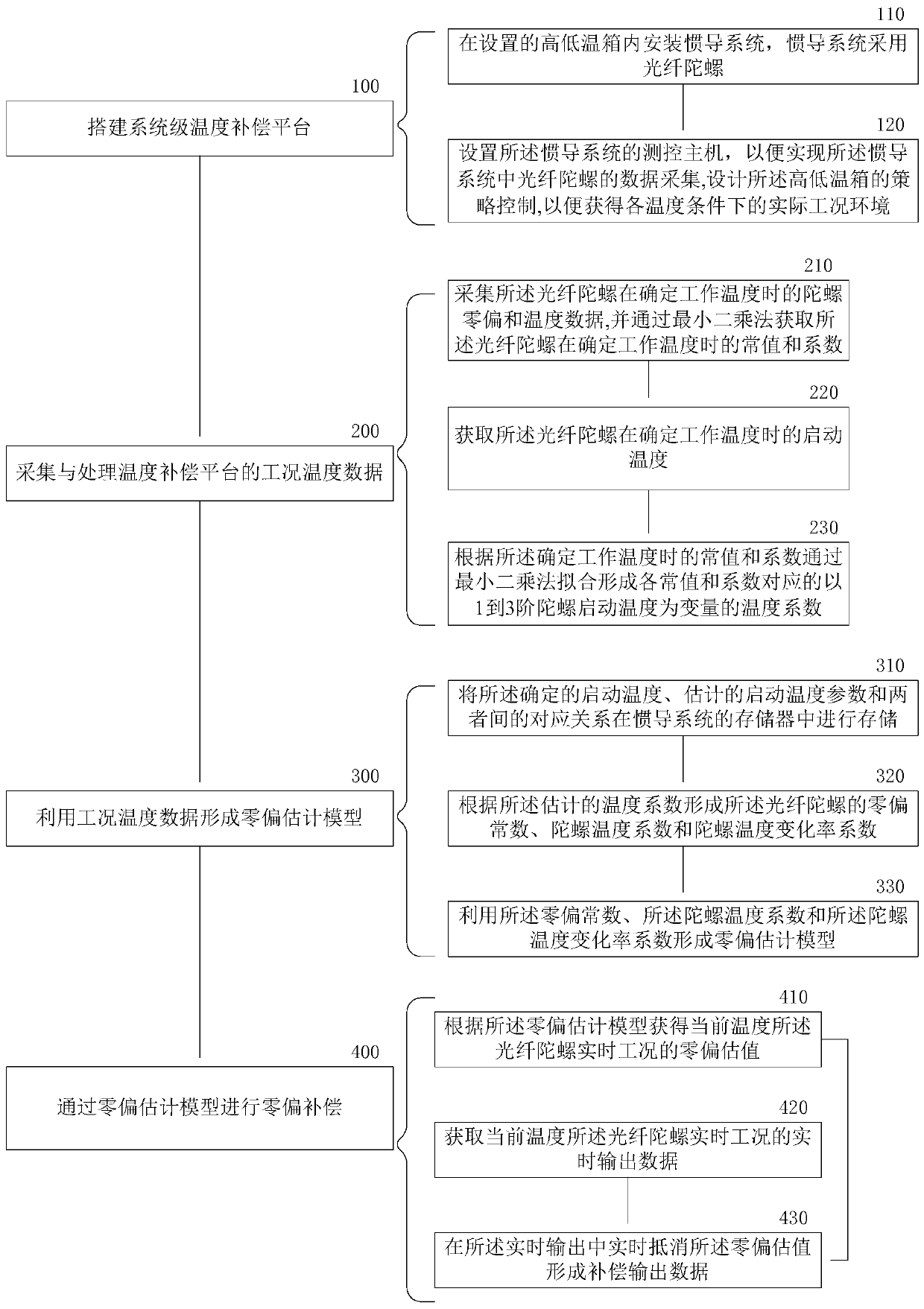
[0047] A fiber optic gyroscope system-level temperature compensation method in an embodiment of the present invention is as follows: figure 1 shown. exist figure 1 , this example includes:

[0048] Step 100: Build a system-level temperature compensation platform.

[0049] Use the pre-assembly program to assemble the fiber optic inertial navigation system to realize the working environment of the fiber optic gyrosco...


PUM


Abstract

The invention provides a fiber-optic gyroscope system level temperature compensation method and device and solves the technical problem that existing temperature compensation is inaccurate. The fiber-optic gyroscope system level temperature compensation method includes the following steps: a system level temperature compensation platform is constructed; working condition and temperature data of the temperature compensation platform are acquired and processed; a zero-offset evaluation model is formed by using the working condition and temperature data; and zero-offset compensation is performedthrough the zero-offset evaluation model. The zero-offset evaluation model of a fiber-optic gyroscope is established in an environment having working conditions of a fiber-optic strapdown inertial group, and measurement deviation formed by system temperature is obtained on the basis of fully reflecting systematic temperature change and a temperature alteration ratio, and is eliminated, thus the north-seeking precision of an optical fiber inertial group in an environment of a total temperature range is ensured.

Description

technical field [0001] The invention relates to the technical field of signal processing, in particular to a fiber optic gyro system-level temperature compensation method and device, and a fiber optic inertial navigation system. Background technique [0002] The fiber optic gyroscope is actually a ring based on the Sagnac effect (a phenomenon in which the rotational speed of the fiber optic coil relative to the inertial space corresponds to the phase difference of the interference light formed between the two light waves propagating counterclockwise and clockwise). Interferometer, so the measurement of the phase difference of the interfering light can measure the angular rate of the sensitive axis of the gyroscope. Because there is a time-varying temperature disturbance in the same section of fiber in the fiber coil, the phase error will be caused by the temperature change when the two beams of light pass through the section of fiber at different times. At the same time, co...

Claims


Application Information

Patent Timeline
Patent Type & Authority Applications(China)
IPC IPC(8): G01C19/72G01C21/16
CPCG01C19/726G01C21/16
Inventor 肖强王盛白焕旭邓志宝赵晓伟余海敏李旬
Owner BEIJING INST OF SPACE LAUNCH TECH
Why Eureka
Try Eureka