Lidar and its detection device

A laser radar and detection device technology, applied in the field of distance measurement, can solve problems such as reducing the use efficiency, increasing the difficulty of laser radar, and complex structural design of detection devices

Active Publication Date: 2021-09-10
HESAI TECH CO LTD
View PDF5 Cites 0 Cited by
  • Summary
  • Abstract
  • Description
  • Claims
  • Application Information

AI Technical Summary

Problems solved by technology

[0003] The existing laser radar mainly adopts the structure design of the through shaft in the structure of the main shaft shaft system. Avoiding the main shaft, the structure design of the detection device is more complicated
Moreover, the multi-line laser radar is a one-to-one transceiver channel, that is, each emitting light source has a photoelectric sensing element corresponding to it. When in use, each pair of emitting light source and photoelectric sensing element needs to be manually aligned. Optical path adjustment, which may increase the difficulty of using lidar and reduce the efficiency of use

Method used


Image

  • Lidar and its detection device
  • Lidar and its detection device
  • Lidar and its detection device

Examples


Embodiment 1

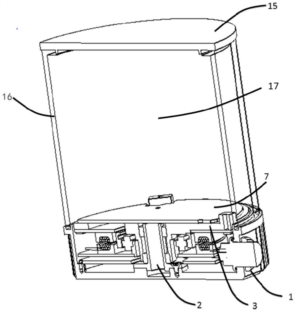
[0060] Embodiment 1 may include a laser radar detection device, including a lens barrel, a beam emitting device, a transmitting lens assembly, a receiving lens assembly, and a photoelectric processing device;

[0061] The lens barrel includes an emitting support body and a receiving support body, and the extending directions of the emitting support body and the receiving support body are parallel to each other;

[0062] The emitting lens assembly is located inside the emitting support and on the optical path of the detection beam emitted by the beam emitting device;

[0063] The receiving lens assembly is located inside the receiving support and on the optical path of the echo beam received by the photoelectric processing device.

Embodiment 2

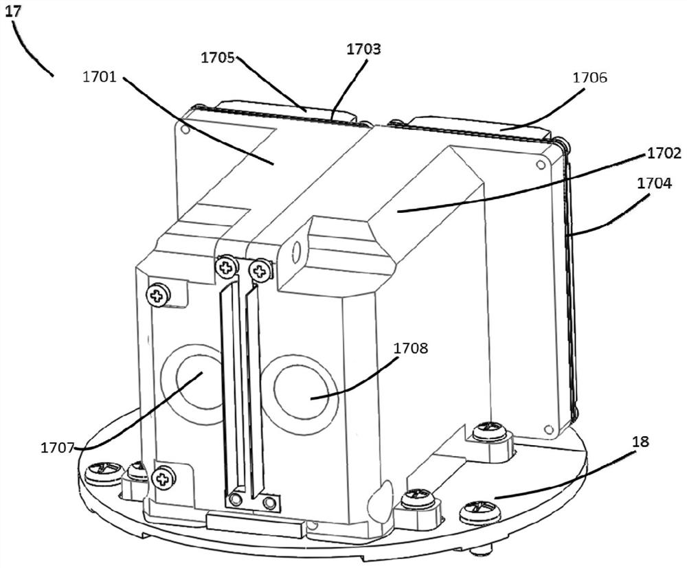
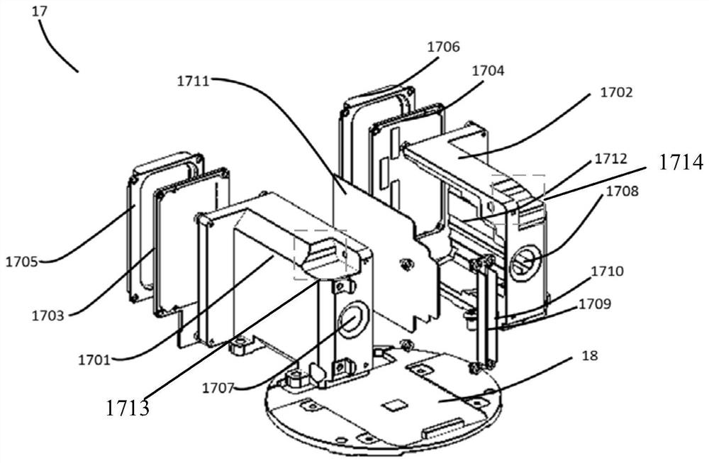
[0064] Embodiment 2 may include the lidar detection device described in Embodiment 1, and the detection device further includes a light barrier, and the light barrier is arranged between the emitting support and the receiving support, and is parallel to the emitting support The extension direction of the body and the receiving support body.

Embodiment 3

[0065] Embodiment 3 may include the lidar detection device described in Embodiment 1 or 2, wherein the beam emitting device includes a emitting circuit board, and the emitting circuit board is located outside the emitting support body and arranged on the emitting The rear end of the support body, wherein the rear end of the emitting support body is the other end opposite to the end where the emitting support body emits the detection beam;

[0066] The photoelectric processing device includes a receiving circuit board, the receiving circuit board is located outside the receiving support body and arranged at the rear end of the receiving support body, wherein the rear end of the receiving support body is connected to the receiving support body The supporting body receives the echo beam at the other end opposite to one end.


PUM


Abstract

The application discloses a laser radar detection device and the laser radar. The detecting device of lidar in the present application comprises: lens barrel, light beam emitting device, emitting lens assembly, receiving lens assembly, and photoelectric processing device; Lens barrel includes emitting support body and receiving support body, and the structure of emitting support body and receiving support body The extension directions are parallel to each other; the emitting lens assembly is located inside the emitting support body and on the optical path of the detection beam emitted by the beam emitting device, and the receiving lens assembly is located inside the receiving support body and located on the optical path of the echo beam received by the photoelectric processing device Above; the beam emitting device and the emitting support are located on one side of a plane, and the photoelectric processing device and the receiving support are located on the other side of the plane. The application makes the outgoing direction of the detection beam and the incident direction of the echo beam approximately parallel, without turning the beam, and the structure of each optical device is relatively simple, reducing or avoiding the adjustment of the alignment optical path.

Description

technical field [0001] The present application relates to the field of ranging, in particular to a laser radar and a detection device thereof. Background technique [0002] LiDAR is a general term for laser active detection sensor equipment. Its working principle is roughly as follows: the transmitter of the laser radar emits a laser beam. After the laser beam encounters an object, it undergoes diffuse reflection, and part of it returns and is received by the laser receiver. , the radar module can calculate the distance between the laser radar and the object according to the time interval of sending and receiving the laser beam multiplied by the speed of light, and then divided by 2. [0003] The existing laser radar mainly adopts the structure design of the through shaft in the structure of the main shaft shaft system. The main shaft extends from the top of the laser radar to the bottom. In this way, when designing the detection device, it is necessary to use a mirror to be...

Claims


Application Information

Patent Timeline
Patent Type & Authority Patents(China)
IPC IPC(8): G01S17/08G01S7/481
CPCG01S17/08G01S7/4817
Inventor 丁林森向少卿
Owner HESAI TECH CO LTD
Why Eureka
Try Eureka