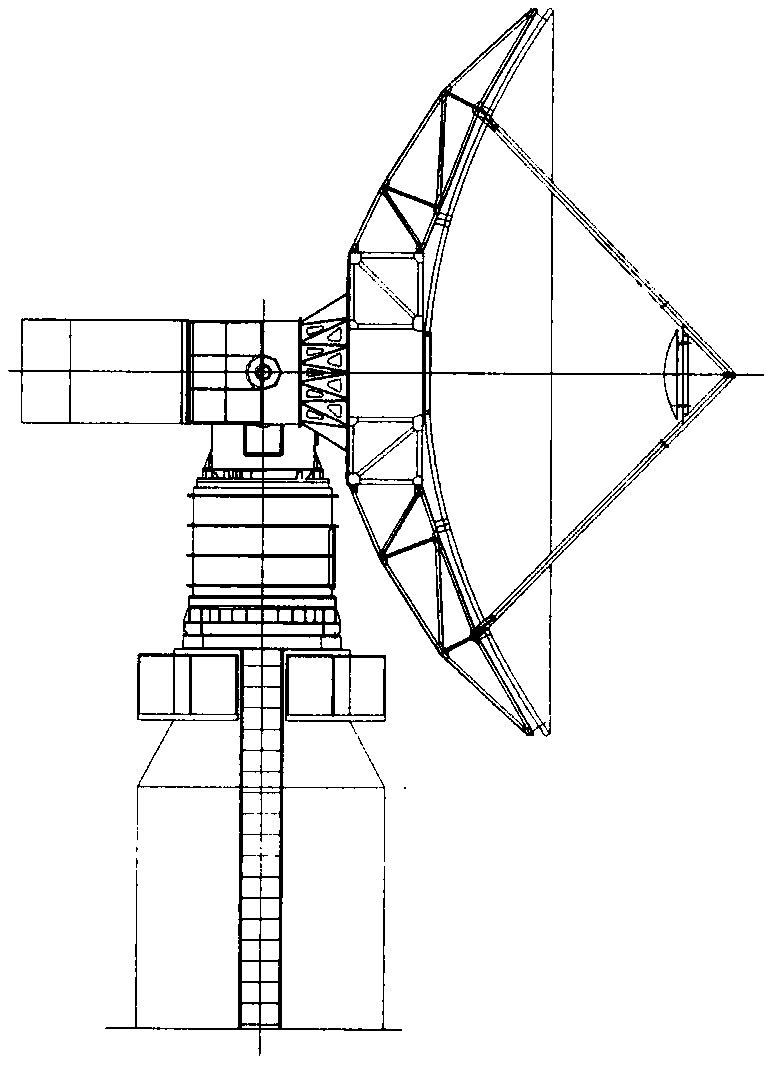
A method and apparatus for correcting three-axis antenna pointing

A three-axis antenna and antenna technology, applied in antennas, special data processing applications, instruments, etc., can solve the problems of increased antenna control error, target deviation from the antenna, and inability to meet the requirements of high-precision pointing correction of the three-axis antenna

Active Publication Date: 2019-10-25
NO 63921 UNIT OF PLA +1
View PDF3 Cites 15 Cited by
  • Summary
  • Abstract
  • Description
  • Claims
  • Application Information

AI Technical Summary

Problems solved by technology

[0004] However, for the three-axis antenna, the origin of the measurement system and the horizon system are not uniform, and considering that the high-speed data transmission receiving task generally works in a higher frequency band, such as X-band and Ka-band, the antenna beam is very narrow at this time, about It is 1 / 4 to 1 / 12 of the S frequency band, so the simple secant compensation can no longer meet the requirements of the three-axis antenna for high-precision pointing correction, which increases the antenna control error and causes the target to deviate from the 3dB beam of the antenna, thereby affecting the signal normal reception, even loss of signal
[0005] According to the parabolic antenna angle error model defined in the existing literature, in the pointing correction, since the model itself contains the correction angle under the measurement system, and it is a trigonometric function of the angle, that is, the solution formula is actually a transcendental equation, so the model cannot be directly solved
The conventional transcendental equation solution method cannot be applied to continuous tracking due to the complexity of the solution process and the difficulty in ensuring real-time performance.

Method used


Image

  • A method and apparatus for correcting three-axis antenna pointing
  • A method and apparatus for correcting three-axis antenna pointing
  • A method and apparatus for correcting three-axis antenna pointing

Examples


Embodiment Construction

[0061] The technical solution of the present invention generally provides a method for pointing correction of a three-axis antenna, and combines the meaning of actual engineering physics to make reasonable and feasible approximations to the intermediate variables in pointing correction, and proposes a real-time online recursive pointing error correction method, The real-time solution of the transcendental equation of the variable to be solved is completed, which ensures the real-time and high-precision completion of program tracking or digital tracking under the working conditions of the high-frequency band of the three-axis antenna.

[0062] The following will start from the principle of the present invention and describe the technical solution of the present invention in conjunction with the accompanying drawings and diagrams accordingly.

[0063] Since the pointing correction method needs to be established on the basis of a given coordinate system and error coefficient, the ...


PUM


Abstract

The invention provides a method and a device for correcting the orientation of a three-axis antenna, and the method comprises the steps: obtaining an approximate value of an orientation angle set by an antenna under an equipment horizon system and an antenna guide angle under an equipment measurement system according to a target position, provided by orbit prediction, under the equipment horizon system through coordinate transformation; obtaining a corresponding pointing angle of the approximate value of the antenna guide angle under the equipment horizon system through correction calculation;and obtaining an accurate value of the antenna guiding angle set by the antenna under the equipment horizon system under the equipment measurement system through recursive calculation and by utilizing the corresponding pointing angle of the approximate value of the antenna guiding angle under the equipment horizon system. By utilizing the method, digital tracking or program tracking can be completed in real time and with high precision under the working condition of the high frequency band of the three-axis antenna.

Description

technical field [0001] The present invention generally relates to the technical field of radio measurement and control. More specifically, the present invention relates to a method and apparatus for correcting the pointing of a triaxial antenna. Background technique [0002] At present, my country's measurement and control satellite ground stations generally use two-axis Cassegrain parabolic antennas, as shown in Figure 1(a). Angle, distance measurement, speed measurement and other data calibration, to obtain high measurement accuracy, used for satellite orbit determination tasks. However, considering that the satellite measurement and control mainly works in the S frequency band, the antenna beam is relatively wide, and the measurement system and the horizon system of the two-axis antenna are the origin of the same coordinate system, so the relatively accurate satellite orbit elements are used to predict the antenna under the horizon system Pointing angle, through secant c...

Claims


Application Information

Patent Timeline
Patent Type & Authority Applications(China)
IPC IPC(8): G06F17/50H01Q3/08
CPCH01Q3/08G06F30/20
Inventor 周晖穆伟张任天黄英高昕李日尚谭元飞赵德阳
Owner NO 63921 UNIT OF PLA
Why Eureka
Try Eureka